X-Bolt Target Rifle Owner's Manual Supplement
X-Bolt Target Rifle Owner's Manual Supplement

WARNING: READ AND PRECISELY FOLLOW ALL INSTRUCTIONS CONTAINED IN THIS OWNER’S MANUAL SUPPLEMENT AND THE OWNER’S MANUAL INCLUDED WITH YOUR FIREARM BEFORE PERFORMING ANY OF THE OPERATIONS OUTLINED IN THIS SUPPLEMENT. PLACE THE “SAFETY” OF YOUR RIFLE IN THE ON SAFE POSITION. REMOVE THE MAGAZINE, OPEN THE ACTION AND MAKE CERTAIN YOUR RIFLE IS COMPLETELY UNLOADED. ALWAYS KEEP THE MUZZLE POINTED IN A SAFE DIRECTION. FAILURE TO FOLLOW THESE WARNINGS COULD RESULT IN SERIOUS INJURY OR DEATH TO YOU OR THOSE AROUND YOU!
WARNING: DISCHARGING FIREARMS IN POORLY VENTILATED AREAS, CLEANING FIREARMS OR HANDLING AMMUNITION MAY RESULT IN EXPOSURE TO LEAD AND OTHER SUBSTANCES KNOWN TO CAUSE BIRTH DEFECTS, REPRODUCTIVE HARM AND OTHER SERIOUS PHYSICAL INJURY. HAVE ADEQUATE VENTILATION AT ALL TIMES. WASH HANDS THOROUGHLY AFTER EXPOSURE.
WARNING: WEAR EYE PROTECTION WHEN MAKING ADJUSTMENTS TO, OR CLEANING YOUR RIFLE TO KEEP PARTS, SOLVENTS OR OTHER AGENTS FROM CONTACTING YOUR EYES, RESULTING IN INJURY.
If your rifle owner’s manual is missing, contact the Browning customer service department immediately at (800) 333-3288 for a free copy, or download one online at browning.com.
DESCRIPTION
DESCRIPTION
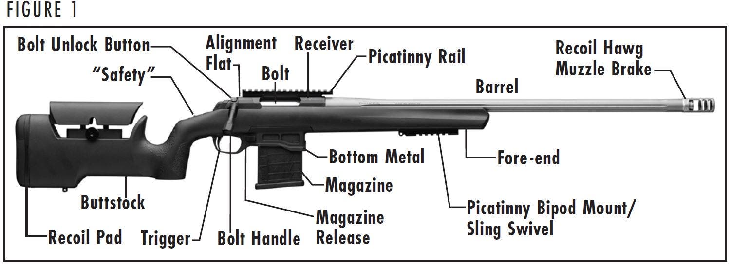
Browning X-Bolt Target rifles are specialized bolt-action models designed for extreme accuracy and the rigors of long-range target shooting competition. These models differ from standard X-Bolt models in a number of ways and require different procedures to perform various operations. These supplemental instructions highlight the areas with procedural variations. For general parts nomenclature, refer to Figure 1.
MAGAZINE
MAGAZINE
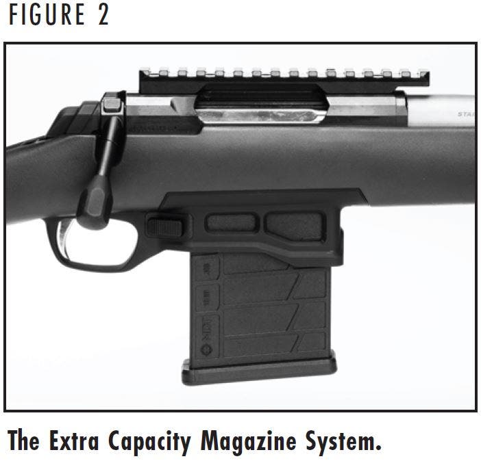
The Browning X-Bolt Target features the Extra Capacity Magazine System and is designed to use the MDT Polymer AICS 10-round detachable box magazine included with the rifle (Figure 2).

NOTICE: WHEN SERVICING THE MAGAZINE, PLEASE FOLLOW ALL INSTRUCTIONS FROM THE MANUFACTURER.
WARNING: REMOVING THE MAGAZINE FROM THE RIFLE DOES NOT PREVENT THE RIFLE FROM BEING FIRED. IF A CARTRIDGE IS IN THE CHAMBER, THE “SAFETY” IS IN THE OFF SAFE POSITION, AND THE TRIGGER IS PULLED, THE RIFLE WILL FIRE EVEN IF NO MAGAZINE IS PRESENT IN THE RIFLE.
REMOVING THE MAGAZINE
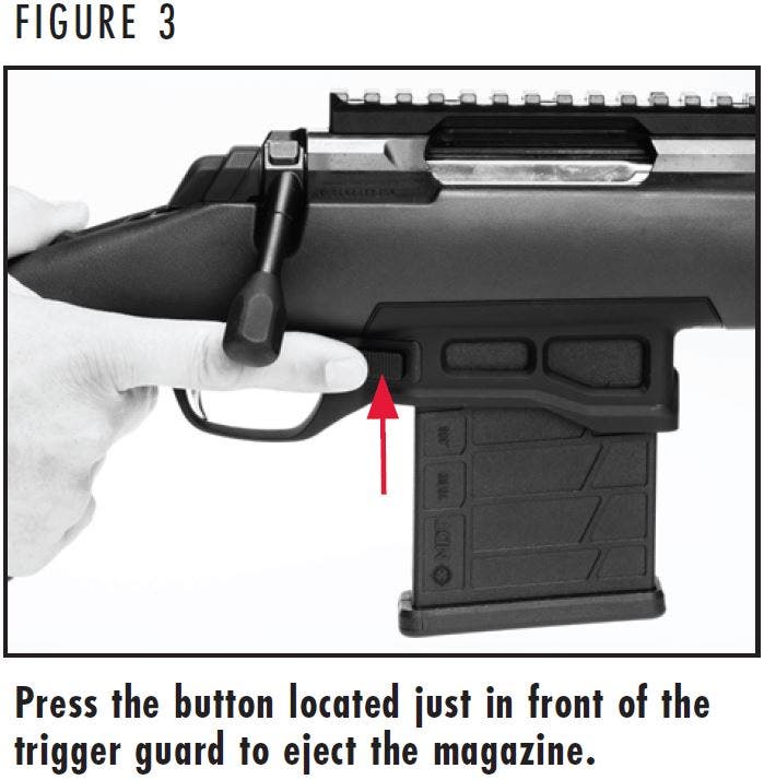
- Eject the magazine from the rifle by pushing the magazine release button located just in front of the trigger guard, on the right side of the rifle (Figure 3). The magazine will drop from the rifle, use your free hand to prevent the magazine from falling to the ground.
WARNING: WHEN LOADING YOUR RIFLE ALWAYS KEEP THE MUZZLE POINTED IN A SAFE DIRECTION, ALWAYS PLACE THE “SAFETY” IN THE ON SAFE POSITION AND KEEP YOUR FINGERS AWAY FROM THE TRIGGER. FAILURE TO FOLLOW THESE WARNINGS COULD RESULT IN SERIOUS INJURY OR DEATH.
WARNING: DO NOT CARRY YOUR RIFLE WITH A CARTRIDGE IN THE CHAMBER TO AVOID ACCIDENTAL DISCHARGE. WHEN FIRING IS NO LONGER IMMINENT, MAKE SURE THE “SAFETY” IS IN THE ON SAFE POSITION AND UNLOAD THE CHAMBER. FAILURE TO FOLLOW THESE WARNINGS COULD RESULT IN SERIOUS INJURY OR DEATH.
LOADING THE MAGAZINE
- Eject the magazine as explained previously.
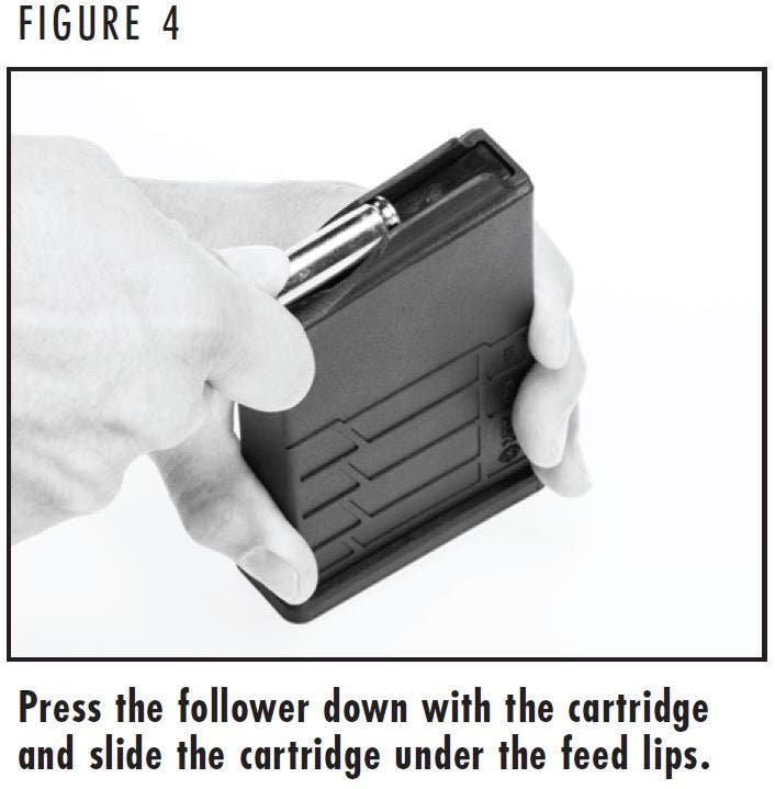
- Place the rim of a cartridge on the follower, just in front of the feed lips.
- Press down on the follower with the rim of the cartridge while simultaneously sliding the cartridge rearward into the magazine under the feed lips (Figure 4). Load subsequent cartridges into the magazine in the same manner.
NOTICE: THE BASE OF EACH CARTRIDGE MUST BE FLUSH WITH THE REAR OF THE MAGAZINE. IF THE NOSE OF A CARTRIDGE PROTRUDES BEYOND THE FRONT OF THE MAGAZINE, IT COULD CAUSE FEEDING PROBLEMS OR INTERFERE WHEN INSERTING THE MAGAZINE INTO THE RIFLE.
WARNING: BEFORE ADJUSTING THE TRIGGER, PLACE THE “SAFETY” IN THE ON SAFE POSITION. REMOVE THE MAGAZINE, OPEN THE ACTION AND MAKE CERTAIN YOUR RIFLE IS COMPLETELY UNLOADED. KEEP THE MUZZLE POINTED IN A SAFE DIRECTION. FAILURE TO FOLLOW THESE WARNINGS COULD RESULT IN SERIOUS INJURY OR DEATH.
TRIGGER ADJUSTMENT
TRIGGER ADJUSTMENT
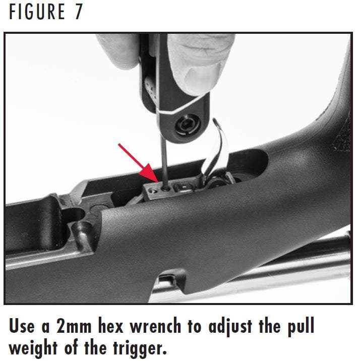
The X-Bolt Target DLX trigger is pre-set at the factory at approximately 2.5 pounds and can be adjusted within a range of approximately 2 to 3.3 pounds by performing the following procedure:
- Remove the magazine from the rifle by pressing the magazine release button. Open the bolt and verify the rifle is unloaded.
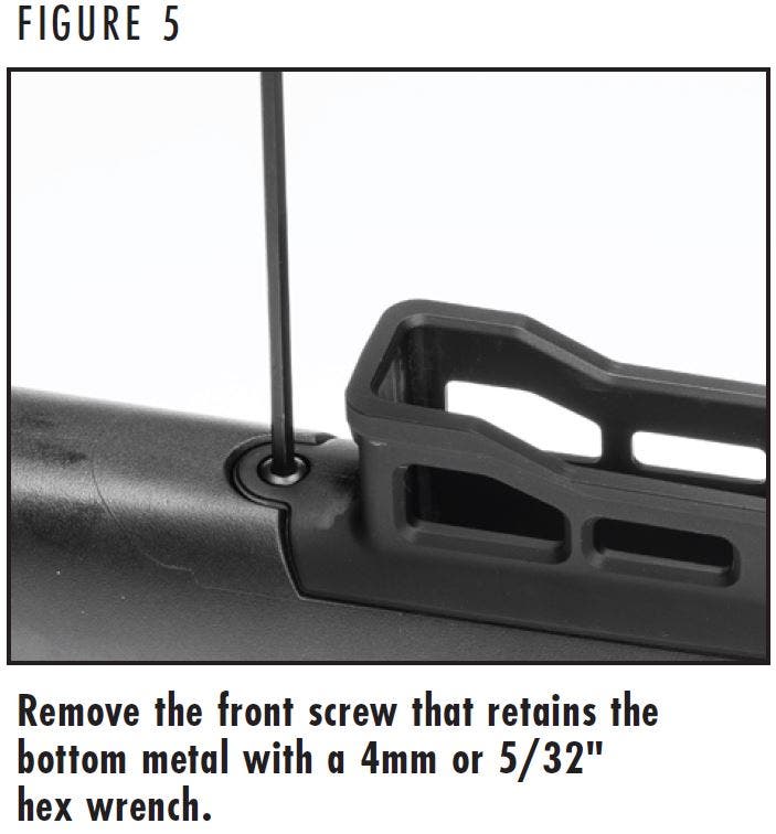
- Remove the front screw that retains the bottom metal with a 4mm or 5/32" hex wrench (Figure 5) by turning the screw counterclockwise.
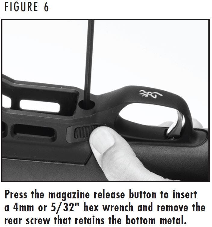
- Push and hold the magazine release button and insert a 4mm or 5/32" hex wrench into the hole in the rear of the bottom metal (Figure 6). Turn the screw counterclockwise to remove it. The bottom metal will lift as the rear screw is loosened.
- Remove the bottom metal from the rifle.
- Carefully remove the red material from the hole closest to the trigger.
- Adjust the trigger by inserting a 2mm hex wrench into the hole closest to the trigger (Figure 7). To increase the weight of the trigger pull, turn the adjustment screw in a clockwise direction. To decrease the weight of the trigger pull, turn the adjustment screw in a counterclockwise direction.
- Trigger pull can be measured, with the rifle unloaded and the bolt closed, using a very accurate spring scale or a commercially available set of trigger pull measuring weights. Most gunsmiths can also measure trigger pull for you.
- When finished making the adjustment, replace the bottom metal back in the stock.
- Install the rear screw first and tighten until it is snug.
- Install the front screw and torque it to 35 in. lb.
- Torque the rear screw to 35 in. lb.
WARNING: BEFORE INSPECTING THE OPTICS RAIL, PLACE THE “SAFETY” IN THE ON SAFE POSITION. REMOVE THE MAGAZINE, OPEN THE ACTION AND MAKE CERTAIN YOUR RIFLE IS COMPLETELY UNLOADED. KEEP THE MUZZLE POINTED IN A SAFE DIRECTION. FAILURE TO FOLLOW THESE WARNINGS COULD RESULT IN SERIOUS INJURY OR DEATH.
OPTICS RAIL
OPTICS RAIL
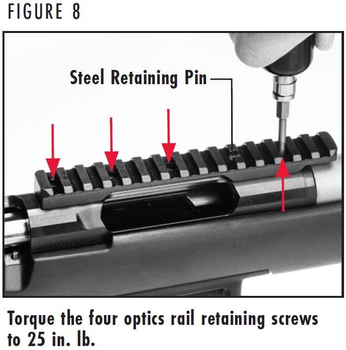
The optics rail is installed at the factory, however, to maintain accuracy, we recommend occasionally inspecting the rail to ensure that the mounting hardware is tight. An additional steel retaining pin also secures the rail to the receiver.
- Place your rifle in a gun vise, on a table or other safe/secure location with the top of the receiver upward. Protect the finish with rags or other padding.
- Remove the scope rings and scope from the optics rail.
- Using a T15 Torx bit, torque the screws to 25 in. lb. (Figure 8). If the mounting screws are loose, remove them and add a drop of removable threadlocker to the screws before torquing the screws.
- Reinstall the scope rings and scope to the rail.
- Sight-in your rifle to confirm zero.