

Browning X-Bolt 2 Owner's Manual
Browning X-Bolt 2 Owner's Manual
Important operating instructions for: Browning X-Bolt 2 Bolt-Action Rifle.
If you have any questions about your new firearm, this owner’s manual or other Browning products, contact:
Browning Consumer Information
One Browning Place
Morgan, UT 84050-9326
Phone: (800) 333-3288
browning.com
Please use the space below to record information about your new firearm.
Model __________________________________________________
Serial Number ____________________________________________
Purchased From __________________________________________
Date of Purchase __________________________________________
THANK YOU FOR CHOOSING BROWNING.
Congratulations on selecting a Browning X-Bolt 2 bolt-action rifle. The X-Bolt 2 is among the most accurate, sophisticated, and finest constructed bolt-action rifles on the market today. This rifle represents the Browning commitment to building the finest firearms available, with the features needed for superior performance and the edge in the field.
With a reasonable amount of care, your X-Bolt 2 rifle should give you many years of dependable, enjoyable service.
Specifications within this owner’s manual are correct at the time of printing and subject to change without notice.
WARNING: YOU ARE RESPONSIBLE FOR FIREARMS SAFETY
WARNING: YOU ARE RESPONSIBLE FOR FIREARMS SAFETY

WARNING: FAILURE TO HEED ANY OF THE FOLLOWING WARNINGS COULD RESULT IN SERIOUS INJURY OR DEATH.
As a gun owner, you accept a set of demanding responsibilities. How seriously you take these responsibilities can be the difference between life and death.
There is no excuse for careless or abusive handling of any firearm. At all times handle this firearm, and all other firearms, with intense respect for their power and potential danger.
Please read and understand all of the cautions, warnings, notices, proper handling procedures and instructions outlined in this owner’s manual before using your new firearm.
1 - ALWAYS KEEP THE MUZZLE OF YOUR FIREARM POINTED IN A SAFE DIRECTION EVEN THOUGH YOU ARE CERTAIN IT IS UNLOADED. Never point any firearm at anything you do not intend to shoot. Be extremely alert and aware of all persons and property within the range of your ammunition.
2 - NEVER RELY TOTALLY ON YOUR FIREARM'S MECHANICAL “SAFETY” DEVICE. LIKE ANY MECHANICAL DEVICE, A "SAFETY" CAN SOMETIMES FAIL; IT CAN BE JARRED OR INADVERTENTLY MANIPULATED INTO AN UNSAFE CONDITION. The word, “safety,” describes a firearm’s trigger block mechanism, sear block mechanism, hammer block mechanism, or firing pin block mechanism. Mechanical “safeties” are designed to place your firearm in a safer status, and no guarantee can be made that the firearm will not fire even if the “safety” is in the on safe position. Mechanical “safeties” merely aid safe gun handling and are no excuse for pointing your firearm’s muzzle in an unsafe direction. See “Operation of the Safety” section below for instructions on the operation of this firearm’s “safety.”
Remember, safe gun handling does not stop with your firearm’s mechanical “safety” devices, it starts there. Always treat this firearm with the respect that you would a loaded, ready-to-fire firearm.
Some firearms do not have a mechanical safety. Many target firearms, lever-action firearms, and pistols do not have manual “safety” mechanisms. Therefore it is critical to read and understand the owner’s manual for every firearm which explains the safe operation of the firearm.
While it is a good idea to “test” your firearm’s mechanical “safety” periodically for proper function, never test the “safety” while your firearm is loaded or pointed in an unsafe direction.
3 - WHENEVER YOU HANDLE ANY FIREARM, OR HAND IT TO SOMEONE, ALWAYS OPEN THE ACTION IMMEDIATELY AND VISUALLY CHECK THE FIREARM'S CHAMBER TO MAKE CERTAIN THAT THE FIREARM IS COMPLETELY UNLOADED. Make certain the firearm does not inadvertently contain any ammunition. Remember, merely removing the magazine does not mean the chamber is unloaded. Always keep the chamber empty and the “safety” in the on safe position unless shooting is imminent.
4 - ALWAYS WEAR EAR AND EYE PROTECTION WHEN SHOOTING. Unprotected, repeated exposure to gunfire can cause hearing damage. Wear hearing protection (shooting ear plugs or muffs) to guard against such damage.
Wear shooting glasses to protect your eyes from flying particles. Allow proper distance (eye relief) between a scope and your eye when firing a scoped pistol, rifle or shotgun. Do not use unorthodox shooting methods that could cause the rearward travel of the slide or bolt of a firearm to contact your eyes, face or hands. Always keep a safe distance between the muzzle of your firearm and any persons nearby, as muzzle blast, debris and ejecting cartridges could inflict serious injury.
Always wear eye protection when disassembling and cleaning any firearm to prevent the possibility of springs, spring-tensioned parts, solvents or other agents from contacting your eyes.
5 - KEEP ALL FIREARMS UNLOADED DURING TRANSPORT, EVEN WHEN STORED IN A HOLSTER, GUN CASE, SCABBARD, OR OTHER CONTAINER.
6 - DROPPING OR JARRING A LOADED FIREARM CAN CAUSE ACCIDENTAL DISCHARGE. This can occur even with the “safety” in the on safe position. Be extremely careful while hunting or during any shooting activity to avoid dropping any firearm.
7 - HUNTING FROM ELEVATED SURFACES SUCH AS TREESTANDS IS DANGEROUS. Doing so may increase the risk of mishandling a firearm. The following rules should always be observed by you and those you hunt with: Always make certain that the stand being used is safe and stable. Always make certain that your firearm is unloaded when it is being taken up and down from the stand. Always make certain that your firearm is not dropped from the stand, or dropped while it is being taken up or down from the stand. Remember, a loaded firearm may discharge when dropped, even with the “safety” in the on safe position.
8 - STORE YOUR FIREARM AND AMMUNITION SEPARATELY, WELL BEYOND THE REACH OF CHILDREN. Take prudent safeguards to ensure your firearm does not become available to untrained, inexperienced or unwelcome hands. Store all firearms in secure, locked cases or a gun safe. Keep your firearm unloaded when not in use.
9 - BEWARE BARREL OBSTRUCTIONS. Mud, snow and an infinite variety of other objects may inadvertently lodge in a barrel bore. It only takes a small obstruction to cause dangerously increased pressures that can damage your firearm and cause serious injury to yourself and others..
BEFORE CHECKING FOR A BARREL OBSTRUCTION, BE CERTAIN YOUR FIREARM IS COMPLETELY UNLOADED, THERE IS NOT A LIVE CARTRIDGE IN THE CHAMBER AND THE “SAFETY” IS IN THE ON SAFE POSITION.
After assuring yourself that the firearm is completely unloaded, open the breech or action and look through the barrel to be sure it is clear of obstructions. If an obstruction is seen, no matter how small it may be, clean the bore with a cleaning rod and patch as described in the Cleaning and Maintenance section of this owner’s manual.
10 - BE ALERT TO THE SIGNS OF AMMUNITION MALFUNCTION. IF YOU DETECT AN OFF SOUND OR LIGHT RECOIL WHEN A CARTRIDGE IS FIRED, DO NOT LOAD ANOTHER CARTRIDGE INTO THE CHAMBER.
If your firearm fails to fire, keep the muzzle pointed in a safe direction for a minimum of 30 seconds. Rotate the ejection area of the firearm away from you, carefully open the action and remove the cartridge from the chamber. If the primer is indented, the defective cartridge should be disposed of in a way that cannot cause harm. If the primer is not indented, your firearm should be examined by a qualified gunsmith and the cause of the malfunction corrected before further use. Glance down the barrel to make sure that no obstructions remain in the barrel. Completely clear the barrel before loading and firing again. Failure to follow these instructions can cause extensive damage to your firearm and possible serious injury to yourself and others.
11 - NEVER INSERT A CARTRIDGE OF THE INCORRECT CALIBER INTO ANY FIREARM. The caliber of your firearm is marked on the barrel. Store all cartridges of different calibers in completely separate and well-marked containers. Never store cartridges of mixed calibers in a common container or in your pockets. See the ammunition section below for more information on the correct ammunition for your firearm.
12 - EXAMINE EVERY CARTRIDGE YOU PUT IN YOUR FIREARM.
We cannot assume any responsibility for the use of unsafe or improper firearm and ammunition combinations or damage or injury caused by damaged ammunition. It is your responsibility to read and heed all warnings in this owner’s manual and on ammunition boxes. See the ammunition section below for more information on the correct ammunition for your firearm.
13 - USE ONLY SAAMI APPROVED AMMUNITION.
The barrel and action of this firearm have been made with substantial safety margins beyond the pressures developed by established American commercial loads. Nevertheless, we can assume no liability for incidents that occur through the use of cartridges of nonstandard dimensions or which develop pressures in excess of commercially available ammunition which have been loaded in accordance with standards established by the Sporting Arms and Ammunition Manufacturers’ Institute (SAAMI).
14 - DISCHARGING FIREARMS IN POORLY VENTILATED AREAS, CLEANING FIREARMS OR HANDLING AMMUNITION MAY RESULT IN EXPOSURE TO LEAD AND OTHER SUBSTANCES KNOWN TO CAUSE BIRTH DEFECTS, REPRODUCTIVE HARM AND OTHER SERIOUS PHYSICAL INJURY. HAVE ADEQUATE VENTILATION AT ALL TIMES. WASH HANDS THOROUGHLY AFTER EXPOSURE.
15 - DO NOT SNAP THE FIRING PIN ON AN EMPTY CHAMBER, THE CHAMBER MAY NOT BE EMPTY!
Treat every firearm with the respect due a loaded firearm, even though you are certain the firearm is unloaded.
16 - KEEP YOUR FINGERS AWAY FROM THE TRIGGER WHILE LOADING AND UNLOADING UNTIL SHOOTING IS IMMINENT.
17 - BE SURE OF YOUR TARGET AND BACKSTOP, PARTICULARLY DURING LOW LIGHT PERIODS. Know the range of your ammunition. Never shoot at water or hard objects.
18 - ALWAYS UNLOAD YOUR FIREARM'S CHAMBER BEFORE CROSSING A FENCE, CLIMBING A TREE, JUMPING A DITCH OR NEGOTIATING OTHER OBSTACLES. Never place your firearm on or against a fence, tree, car, or other similar object.
19 - BE DEFENSIVE AND ON GUARD AGAINST UNSAFE GUN HANDLING AROUND YOU AND OTHERS. Don’t be timid when it comes to firearm safety. If you observe other shooters violating any of these safety precautions, politely suggest safer handling practices.
20 - BE CERTAIN YOUR FIREARM IS UNLOADED BEFORE CLEANING.
Special and extreme care should be taken to be sure your firearm is unloaded before disassembly, cleaning, and reassembly. Keep ammunition away from the cleaning location. Never test the mechanical function of any firearm with live ammunition.
21 - TEACH AND SUPERVISE FIREARMS SAFETY TO ALL MEMBERS OF YOUR FAMILY, ESPECIALLY TO CHILDREN AND NON-SHOOTERS. Closely supervise newcomers to the shooting sports. Encourage enrollment in hunting and shooting safety courses.
22 - NEVER DRINK ALCOHOLIC BEVERAGES OR TAKE ANY TYPE OF DRUGS BEFORE OR DURING SHOOTING. Your vision, motor skills, and judgment could be dangerously impaired, making your gun handling unsafe to you and to others.
23 - READ AND HEED ALL WARNINGS IN THIS OWNER'S MANUAL, ON AMMUNITION BOXES, AND WITH ALL ACCESSORIES THAT YOU INSTALL ON YOUR FIREARM. It is your responsibility to secure the most up-to-date information on the safe handling procedures of your Browning firearm. We assume no liability for incidents that occur when unsafe or improper firearm accessories or ammunition combinations are used.
24 - PRACTICE PERIODIC MAINTENANCE, AVOID UNAUTHORIZED SERVICING. Your firearm is a mechanical device that will not last forever, and as such, is subject to wear and requires periodic inspection, adjustment and service. Browning firearms should be serviced by a Browning Recommended Service Center or by our Service Facility in Arnold, Missouri. We cannot assume any responsibility for injuries suffered or caused by unauthorized servicing, alterations or modifications of Browning firearms.
25 - DO NOT, UNDER ANY CIRCUMSTANCES, ALTER THE TRIGGER, SAFETY OR OTHER PARTS OF THE FIRING MECHANISM OF THIS OR ANY OTHER FIREARM EXCEPT AS OTHERWISE DESCRIBED IN THIS MANUAL.
WE RESERVE THE RIGHT TO REFUSE SERVICE ON FIREARMS THAT HAVE BEEN ALTERED, ADDED TO OR SUBSTANTIALLY CHANGED. Removal of metal from the barrel, or modifications of the firing mechanism and/or operating parts, may lead to a refusal of service on such firearms. You will be charged for parts and labor to return the firearm to original specifications prior to servicing your firearm.
With respect to AFTERMARKET PARTS OR COMPONENTS (including, for example, aftermarket trigger systems, barrels, muzzle brakes, suppressors, magazines, etc.), USE AT YOUR OWN RISK. Browning firearms are designed and engineered to meet stringent safety standards. Browning is not responsible for personal injuries or property damage caused by alterations to a firearm. This includes the incorporation of aftermarket parts or components that may or may not satisfy Sporting Arms and Ammunition Manufacturers’ Institute (SAAMI) standards (for example, an aftermarket trigger system may not satisfy SAAMI minimum trigger pull standards, etc.) or may create other dangerous conditions. These conditions may or may not be apparent to the user (for example, installing an aftermarket barrel may have the effect of altering critical firearm dimensions, including headspace, and may create an unsafe firing condition, etc.). Aftermarket parts or components that do not satisfy SAAMI standards, or that could create other dangerous conditions, should not be used.
FAILURE TO FOLLOW THIS WARNING COULD RESULT IN SERIOUS INJURY OR DEATH, AS WELL AS CAUSE DAMAGE TO YOUR FIREARM.
BE CAREFUL!
BE CAREFUL!
GENERAL DESCRIPTION AND OPERATION
The Browning X-Bolt 2 is a bolt-action rifle that operates by lifting the bolt handle, drawing the bolt rearward, sliding the bolt forward, and rotating the bolt downward until it stops. This process takes a cartridge from the magazine and loads it into the chamber for firing.
The X-Bolt 2 has a strong three-lug bolt and features a short, 60° bolt lift that lets you cycle the action rapidly for quick follow-up shots. Because the bolt handle does not swing up as high as other bolt-action rifles there is ample clearance for the hand with large optics.
The design of the receiver reduces weight while retaining the strength to handle magnum calibers. Other notable features include a detachable box magazine and thumb-operated top-tang “safety” that works in conjunction with the bolt unlock button.
NOMENCLATURE
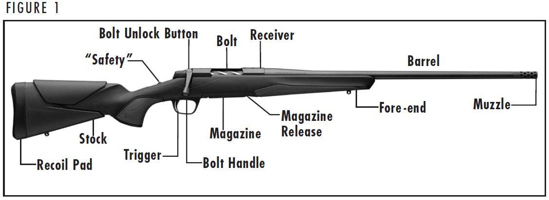
In conventional firearm terminology the position and movement of firearm parts are described as they occur with the firearm horizontal and in the normal firing position: i.e., the muzzle is forward or in front; the buttstock is rearward or to the rear; the trigger is downward or underneath; the scope is upward or on top. For general parts nomenclature, refer to Figure 1.
SERIAL NUMBER
The serial number of your firearm can be found on the right side of the receiver, in front of the bolt handle.
WARNING: ALWAYS KEEP THE “SAFETY” IN THE ON SAFE POSITION UNLESS SHOOTING IS IMMINENT. ALWAYS KEEP THE MUZZLE POINTED IN A SAFE DIRECTION. FAILURE TO FOLLOW THESE WARNINGS COULD RESULT IN SERIOUS INJURY OR DEATH.
Operation of the "Safety"
Operation of the "Safety"
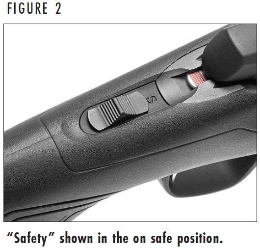
The “safety” is located on the top tang at the rear of the receiver. When the “safety” is drawn to the rear, the firearm is in the on safe position (Figure 2). This blocks the trigger and locks the bolt in the closed position. In this position an “S” will appear on the tang in front of the “safety.”
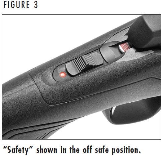
When the “safety” is pushed forward, the “S” will be covered and a red dot will appear indicating that the rifle is in the “off safe” position and ready to fire (Figure 3).
WARNING: DO NOT DEPEND ON THE RED COLOR ALONE TO INDICATE YOUR FIREARM’S SAFETY STATUS. TIME, EXPOSURE TO THE ELEMENTS, AND THE ABRASIVE ACTION OF CLEANING AGENTS CAN ERASE IT. FAILURE TO FOLLOW THIS WARNING COULD RESULT IN SERIOUS INJURY OR DEATH.
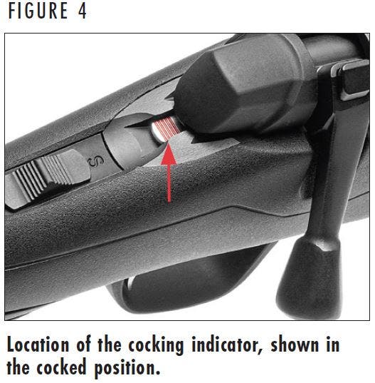
Cocking Indicator
Cocking Indicator
Below the bolt shroud and ahead of the “safety” is a serrated cocking indicator. The indicator is painted red. When the rifle is cocked, the cocking indicator may be readily felt with the thumb as well as easily seen with a quick glance (Figure 4). When the rifle is fired, the cocking indicator retracts into the bolt shroud and cannot be seen or felt.
WARNING: DO NOT DEPEND ON THE RED COLOR ALONE TO INDICATE YOUR FIREARM’S SAFETY STATUS. TIME, EXPOSURE TO THE ELEMENTS, AND THE ABRASIVE ACTION OF CLEANING AGENTS CAN ERASE IT. FAILURE TO FOLLOW THIS WARNING COULD RESULT IN SERIOUS INJURY OR DEATH.
WARNING: DO NOT DEPEND ON THE RED COLOR ALONE TO INDICATE YOUR FIREARM’S SAFETY STATUS. TIME, EXPOSURE TO THE ELEMENTS, AND THE ABRASIVE ACTION OF CLEANING AGENTS CAN ERASE IT. FAILURE TO FOLLOW THIS WARNING COULD RESULT IN SERIOUS INJURY OR DEATH.
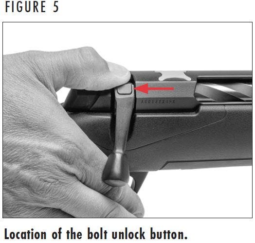
Bolt Unlock Button
Bolt Unlock Button
The bolt unlock button on the X-Bolt 2 rifle is located on the upper part of the bolt handle (Figure 5). The bolt unlock button works in conjunction with the top-tang “safety” and allows the bolt to be operated to unload a cartridge from the chamber with the “safety” in the on safe position. To unload the chamber with the “safety” in the on safe position, simply press the bolt unlock button down and rotate the bolt upward, then draw the bolt handle completely rearward.
Initial Cleaning
Initial Cleaning
Various exposed metal parts of your new firearm have been coated at the factory with a rust preventative compound. A fine, light gun oil is ideal for removing this compound and for giving your new firearm its first lubrication. Before shooting your firearm, clean the anti-rust compound from the inside of the barrel, receiver, and the action/chamber areas. Clean the barrel using a cleaning rod and patch as explained under the “Cleaning and Maintenance Suggestions” section. If your X-Bolt 2 rifle is to be stored, it is acceptable to leave the rust preventative compound on the rifle and keep it in its original packaging.
WARNING: BEFORE INSERTING OR REMOVING THE BOLT, ENSURE THAT THE “SAFETY” IS IN THE ON SAFE POSITION. ALWAYS KEEP THE MUZZLE POINTED IN A SAFE DIRECTION. VISUALLY INSPECT THE CHAMBER TO BE ABSOLUTELY CERTAIN THE FIREARM IS COMPLETELY UNLOADED. FAILURE TO FOLLOW THIS WARNING COULD RESULT IN SERIOUS INJURY OR DEATH.
Inserting and Removing the Bolt
Inserting and Removing the Bolt
Inserting the Bolt
The X-Bolt 2 rifle comes packed in a foam-padded box with the bolt removed from the rifle. To install the bolt into the receiver perform the following procedure:
- Ensure the “safety” is in the on safe position.
- Align the forward end of the bolt in the rear opening of the receiver.
- Push the bolt completely forward and rotate the handle down to lock it. It is not necessary to depress the bolt stop to insert the bolt, but you may do so to ease the installation.
The rifle is now completely assembled and may be operated normally.
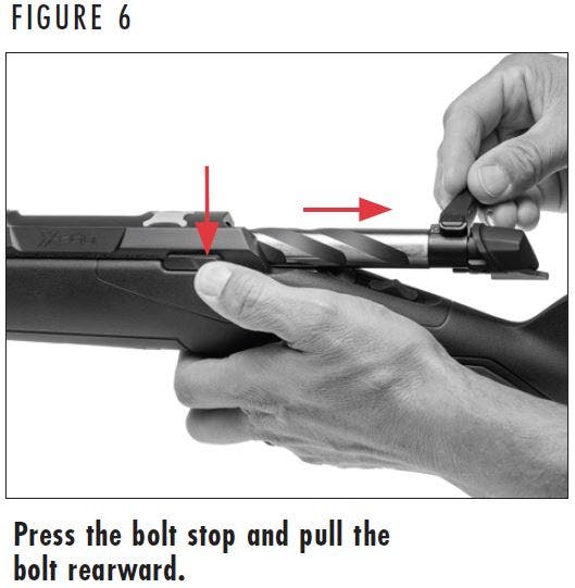
Removing the Bolt
- Ensure the “safety” is in the on safe position.
- Press the bolt unlock button and rotate the bolt handle upward.
- The bolt stop is the horizontal bar on the left side of the receiver. Press inward on the rear end of the bolt stop and carefully draw the bolt to the rear and out of the receiver (Figure 6).

NOTICE: WHEN REMOVING THE BOLT FROM THE RECEIVER, TAKE CARE TO PREVENT THE COCKING INDICATOR FROM STRIKING AND DAMAGING THE COMB OF THE STOCK.
WARNING: DISCHARGING FIREARMS IN POORLY VENTILATED AREAS, CLEANING FIREARMS OR HANDLING AMMUNITION MAY RESULT IN EXPOSURE TO LEAD AND OTHER SUBSTANCES KNOWN TO CAUSE BIRTH DEFECTS, REPRODUCTIVE HARM AND OTHER SERIOUS PHYSICAL INJURY. HAVE ADEQUATE VENTILATION AT ALL TIMES. WASH HANDS THOROUGHLY AFTER EXPOSURE.
DO NOT USE AMMUNITION OTHER THAN WHAT IS INSCRIBED ON THE RIGHT SIDE OF THE BARREL. EXAMINE EVERY CARTRIDGE YOU PUT IN YOUR FIREARM.
Ammunition
Ammunition
The barrel and action of this firearm have been made with safety margins over the pressures established by the Sporting Arms and Ammunition Manufacturers’ Institute (SAAMI) for Service Cartridges. However, we assume no responsibility for incidents which occur through the use of cartridges of nonstandard dimension or those developing pressures in excess of SAAMI established standards.
Magazine
Magazine
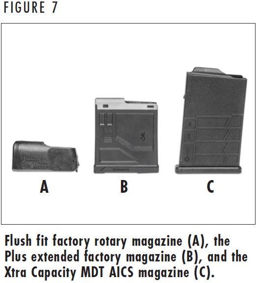
MAGAZINE TYPES
Depending on the configuration, Browning X-Bolt 2 rifles utilize one of the three different types of magazines shown in Figure 7.
WARNING: REMOVING THE MAGAZINE FROM THE RIFLE DOES NOT PREVENT THE RIFLE FROM BEING FIRED. IF A CARTRIDGE IS IN THE CHAMBER, THE “SAFETY” IS IN THE OFF SAFE POSITION, AND THE TRIGGER IS PULLED, THE RIFLE WILL FIRE EVEN IF NO MAGAZINE IS PRESENT IN THE RIFLE.
ROTARY MAGAZINE
Some Browning X-Bolt 2 rifles utilize the Browning detachable rotary magazine (Figure 7) that fits flush with the bottom of the rifle. Information on loading this magazine can be found on Figure 9. The magazine capacity for standard calibers is four cartridges. The magazine capacity for magnum and WSM calibers is three cartridges.
NOTICE: DO NOT TAMPER WITH THE ASSEMBLY SCREW ON THE REAR OF THE MAGAZINE. DOING SO WILL RENDER THE MAGAZINE INOPERATIVE.
BROWNING PLUS MAGAZINE
Some Browning rifles include the Plus Magazine System that offers additional magazine capacity (Figure 7). Information on loading this magazine can be found on Figures 11. The Plus Magazine capacity for standard calibers is six cartridges. The magazine capacity for magnum and WSM calibers is five cartridges.
NOTICE: DO NOT TAMPER WITH THE ASSEMBLY SCREW ON THE REAR OF THE MAGAZINE. DOING SO WILL RENDER THE MAGAZINE INOPERATIVE.
XTRA CAPACITY MAGAZINE SYSTEM
Some Browning X-Bolt Target rifles feature the Xtra Capacity Magazine System (Figure 7). Information on loading this magazine can be found on Figure 13. These rifles use the MDT Polymer AICS 10-round detachable box magazine included with the rifle.
NOTICE: WHEN SERVICING THE MAGAZINE, PLEASE FOLLOW ALL INSTRUCTIONS FROM THE MANUFACTURER.
WARNING: WHEN LOADING YOUR RIFLE ALWAYS KEEP THE MUZZLE POINTED IN A SAFE DIRECTION, ALWAYS PLACE THE “SAFETY” IN THE ON SAFE POSITION AND KEEP YOUR FINGERS AWAY FROM THE TRIGGER. FAILURE TO FOLLOW THESE WARNINGS COULD RESULT IN SERIOUS INJURY OR DEATH.
DO NOT CARRY YOUR RIFLE WITH A CARTRIDGE IN THE CHAMBER TO AVOID ACCIDENTAL DISCHARGE. WHEN FIRING IS NO LONGER IMMINENT, MAKE SURE THE “SAFETY” IS IN THE ON SAFE POSITION AND UNLOAD THE CHAMBER. FAILURE TO FOLLOW THESE WARNINGS COULD RESULT IN SERIOUS INJURY OR DEATH.
NOTICE: THE BASE OF EACH CARTRIDGE MUST BE FLUSH WITH THE REAR OF THE MAGAZINE. IF THE NOSE OF A CARTRIDGE PROTRUDES BEYOND THE FRONT OF THE MAGAZINE, IT COULD CAUSE FEEDING PROBLEMS OR INTERFERE WHEN INSERTING THE MAGAZINE INTO THE RIFLE.
Loading
Loading
There are two methods used to load a cartridge into the chamber of the X-Bolt 2 rifle: Loading from the magazine and through the ejection port.
LOADING THE MAGAZINE
BROWNING ROTARY MAGAZINE
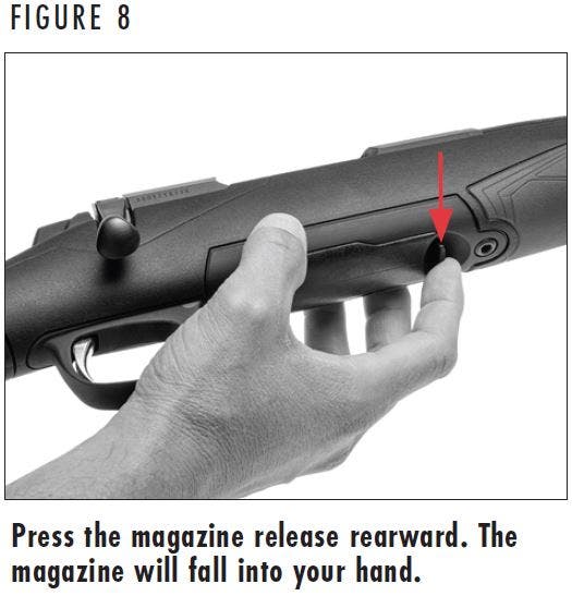
- Eject the magazine from the rifle by pulling the magazine release, located on the forward edge of the magazine, rearward with your index finger. The magazine will drop into your hand (Figure 8).
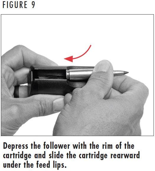
- Place the rim of a cartridge on the front of the follower and press down on the follower with the rim of the cartridge while simultaneously sliding the cartridge rearward into the magazine under the feed lips (Figure 9). Load subsequent cartridges into the magazine in the same manner.
BROWNING PLUS EXTENDED MAGAZINE
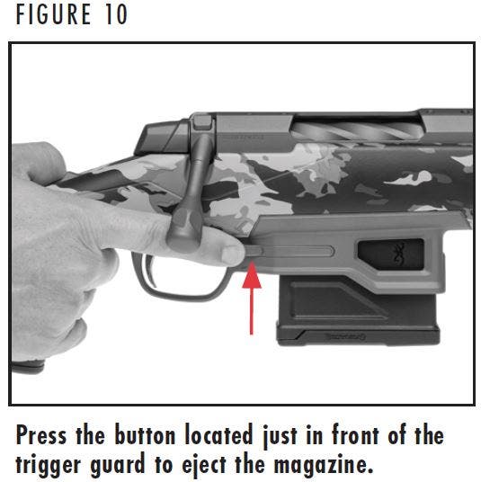
- Eject the magazine from the rifle by pushing the magazine release button located just in front of the trigger guard, on the right side of the rifle (Figure 10). The magazine will drop from the rifle, use your free hand to prevent the magazine from falling to the ground.
- Place the rim of a cartridge on the follower, just in front of the feed lips.
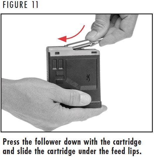
- Press down on the follower with the rim of the cartridge while simultaneously sliding the cartridge rearward into the magazine under the feed lips (Figure 11). Load subsequent cartridges into the magazine in the same manner.
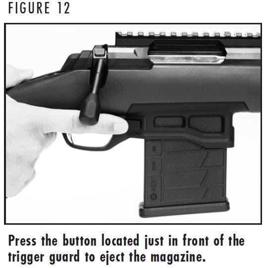
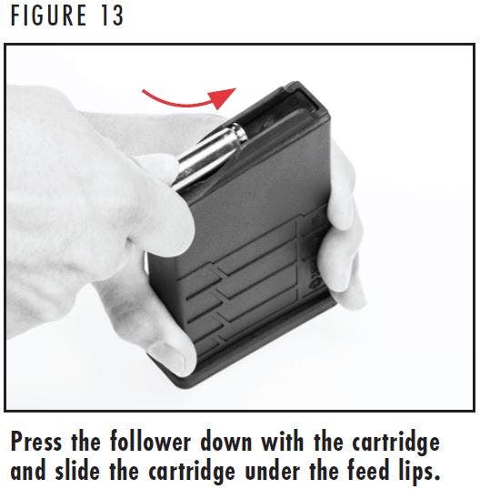
MDT AICS MAGAZINE
- Eject the magazine from the rifle by pushing the magazine release button located just in front of the trigger guard, on the right side of the rifle (Figure 12). The magazine will drop from the rifle, use your free hand to prevent the magazine from falling to the ground.
- Place the rim of a cartridge on the follower, just in front of the feed lips.
- Press down on the follower with the rim of the cartridge while simultaneously sliding the cartridge rearward into the magazine under the feed lips (Figure 13). Load subsequent cartridges into the magazine in the same manner.
LOADING THE CHAMBER FROM THE MAGAZINE
- Ensure that the “safety” in the on safe position.
- Remove the magazine from the rifle as explained previously.
- Pull the bolt completely rearward and inspect the chamber to make sure it is empty.
- Close the bolt.
- Load the magazine as explained previously.
- Insert the loaded magazine into the rifle by inserting it into the magazine well until it is retained in place by the magazine catch.
- When ready to shoot, load the chamber by pressing the bolt unlock button and simultaneously lifting the bolt handle completely up. Release the bolt unlock button and draw the bolt completely rearward, then push the bolt forward and rotate the bolt handle down.
- Immediately verify that the “safety” is in the on safe position.
WARNING: THE RIFLE IS NOW READY TO FIRE BY SIMPLY MOVING THE “SAFETY” TO THE OFF SAFE POSITION AND PULLING THE TRIGGER.
SINGLE-SHOT LOADING FROM THE MAGAZINE
To use your X-Bolt 2 as a single-shot rifle, it is recommended that you use the following single-shot loading procedure.
- Ensure that the “safety” in the on safe position.
- Remove the magazine from the rifle as explained previously.
- Pull the bolt completely rearward and inspect the chamber to make sure it is empty.
- Close the bolt.
- Load a single cartridge into the magazine.
- Insert the loaded magazine into the rifle by inserting it into the magazine well until it is retained in place by the magazine catch.
- When ready to shoot, load the single cartridge into the chamber by pressing the bolt unlock button and simultaneously lifting the bolt handle completely up. Release the bolt unlock button and draw the bolt completely rearward, then push the bolt forward and rotate the bolt handle down.
- Immediately verify that the “safety” is in the on safe position.
WARNING: THE RIFLE IS NOW READY TO FIRE BY SIMPLY MOVING THE “SAFETY” TO THE OFF SAFE POSITION AND PULLING THE TRIGGER.
SINGLE SHOT LOADING DIRECTLY TO THE CHAMBER
You may also load your rifle by placing a cartridge directly into the chamber. To load the rifle in this manner, use the following loading procedure.
- Ensure that the “safety” in the on safe position.
- Insert an unloaded magazine into the rifle.
- Pull the bolt rearward and inspect the chamber to make sure it is empty.
- Insert a single cartridge into the ejection port and place it on top of the unloaded magazine.
- When ready to shoot, push the bolt completely forward and rotate the bolt handle down to load the single cartridge into the chamber.
- Immediately verify that the “safety” is in the on safe position.
WARNING: THE RIFLE IS NOW READY TO FIRE BY SIMPLY MOVING THE “SAFETY” TO THE OFF SAFE POSITION AND PULLING THE TRIGGER.
WARNING: NEVER MOVE THE “SAFETY” FROM THE ON SAFE POSITION OR CHAMBER A CARTRIDGE UNLESS SHOOTING IS IMMINENT. ALWAYS KEEP THE MUZZLE POINTED IN A SAFE DIRECTION. FAILURE TO FOLLOW THESE WARNINGS COULD RESULT IN SERIOUS INJURY OR DEATH.
Firing
Firing
- Ensure that the “safety” is in the on safe position.
- Load a cartridge into the chamber (as explained previously) from the magazine or directly to the chamber.
- With a cartridge in the chamber, you need only move the “safety” to the off safe position to make the rifle ready for firing.
- When ready to fire, move the “safety” into the off safe position, take aim, and squeeze the trigger.
- After a cartridge is fired, cycle the bolt rearward to eject the empty case. If you wish to continue shooting, push the bolt fully forward. This picks up a loaded cartridge from the magazine and chambers it. You may continue to load and fire the rifle in this manner until the magazine is empty.
- If you are done shooting, leave the bolt to the rear, with the breech in the open position so that you may visually inspect the chamber, bore, and magazine to be sure they contain no cartridges.
WARNING: EVEN WITH THE BOLT OPEN AFTER SHOOTING, DO NOT ASSUME THE RIFLE IS UNLOADED. ALWAYS INSPECT THE CHAMBER, BARREL, FEED MECHANISM AND MAGAZINE TO BE CERTAIN THE RIFLE IS COMPLETELY UNLOADED. FAILURE TO FOLLOW THESE WARNINGS COULD RESULT IN SERIOUS INJURY OR DEATH.
WARNING: WHEN UNLOADING YOUR RIFLE ALWAYS PLACE THE “SAFETY” IN THE ON SAFE POSITION. KEEP THE MUZZLE POINTED IN A SAFE DIRECTION AND YOUR FINGERS AWAY FROM THE TRIGGER. FAILURE TO FOLLOW THESE WARNINGS COULD RESULT IN SERIOUS INJURY OR DEATH.
ALWAYS INSPECT THE CHAMBER, BARREL AND MAGAZINE CAREFULLY AFTER UNLOADING TO BE SURE ALL LIVE CARTRIDGES ARE CLEARED FROM THE FIREARM.
REMOVING THE MAGAZINE FROM THE RIFLE DOES NOT PREVENT THE RIFLE FROM BEING FIRED. IF A CARTRIDGE IS IN THE CHAMBER, THE “SAFETY” IS IN THE OFF SAFE POSITION, AND THE TRIGGER IS PULLED, THE RIFLE WILL FIRE EVEN IF NO MAGAZINE IS PRESENT IN THE RIFLE.
Unloading
Unloading
- Ensure that the “safety” is in the on safe position.
- Open the bolt and eject any cartridge in the chamber. Leave the bolt in the rearward position with the action open.
- Look into the chamber to verify that it is unloaded.
- Push the magazine release button rearward and remove the magazine.
- With the chamber empty and the magazine removed, close the bolt.
- Strip the cartridges from the magazine as explained below and insert the empty magazine into the magazine well of the rifle.
UNLOADING THE MAGAZINE
- Remove the magazine from the rifle as explained previously.
- Unload the chamber of the rifle as previously explained.
- Strip the cartridges from the magazine by pushing forward on the rim of the top cartridge and sliding each cartridge out, one at a time.
- Unload any extra magazines.
WARNING: BEFORE MOUNTING A SCOPE, SIGHT OR OTHER ACCESSORIES TO YOUR RIFLE, PLACE THE “SAFETY” IN THE ON SAFE POSITION. OPEN THE ACTION AND MAKE CERTAIN YOUR RIFLE IS COMPLETELY UNLOADED. KEEP THE MUZZLE POINTED IN A SAFE DIRECTION. FAILURE TO FOLLOW THESE WARNINGS COULD RESULT IN SERIOUS INJURY OR DEATH.
Mounting a Scope
Mounting a Scope
HUNTING AND LONG RANGE MODELS
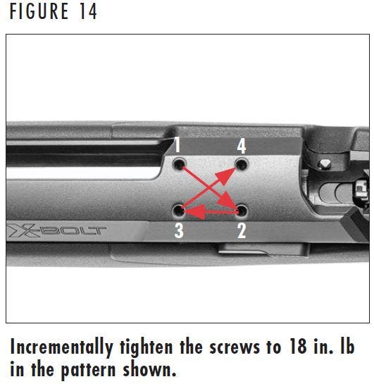
The top of hunting and long range X-Bolt 2 receivers are drilled and tapped for scope bases. Unlike other centerfire rifles, these X-Bolt 2 rifles utilize four screws per scope base instead of two for attaching each base to the receiver. From the factory, the scope base holes are fitted with polymer thread protectors.
NOTICE: ALWAYS USE THE CORRECT BASES FOR THIS RIFLE AND THE APPROPRIATE LENGTH SCREWS.
- Remove the magazine from the rifle as explained previously.
- Place your rifle in a gun vise or on a table or other safe / secure location with the top of the receiver upward. Protect the finish with rags or other padding.
- You should have a compatible one- or two-piece style base and eight screws of the correct length.
- Clean all oil, grease or dirt from the receiver top and from the scope base parts.
- Remove the two X-shaped thread protectors from the top of the receiver.
- Pre-position the bases on the receiver top to determine the best orientation of the bases.
- Insert the screws through the bases and start each screw into its respective hole in the receiver. Be careful to ensure that the threads of each screw engage properly in the receiver threads to prevent stripping the threads in the receiver. Do not tighten the screws.
- You must use screws of the appropriate length to ensure proper thread engagement. Once the bases are installed, check inside the receiver to verify that the base mounting screws are not too long and interfering with the operation of the bolt.
- Many gunsmiths find it helpful to use a drop of serviceable thread locking compound to ensure the screws stay tight. Make sure the thread locking compound does not get into the action.
- Tighten the screws evenly to 18 in. lb in the pattern shown in Figure 14. This will allow the screws to be tightened with equal pressure.
- Mount your scope rings and scope as outlined in the instructions supplied with your scope rings and / or scope. Always make sure you have the proper eye relief.
WARNING: BEFORE INSPECTING THE OPTICS RAIL, PLACE THE “SAFETY” IN THE ON SAFE POSITION. REMOVE THE MAGAZINE, OPEN THE ACTION, AND MAKE CERTAIN YOUR RIFLE IS COMPLETELY UNLOADED. KEEP THE MUZZLE POINTED IN A SAFE DIRECTION. FAILURE TO FOLLOW THESE WARNINGS COULD RESULT IN SERIOUS INJURY OR DEATH.
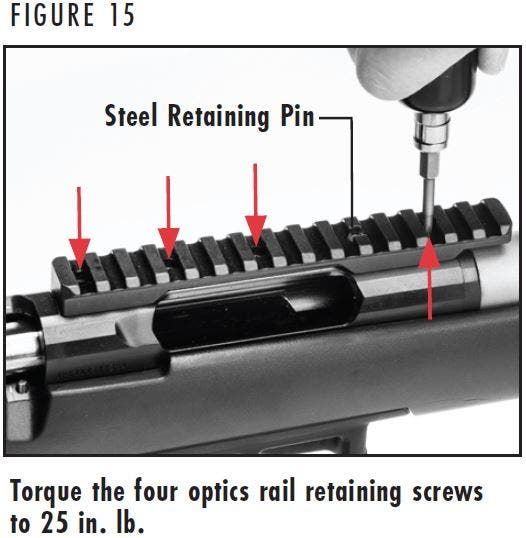
X - BOLT 2 TARGET MODELS
X-Bolt 2 Target models include a factory-installed optics rail. To maintain accuracy, we recommend occasionally inspecting the rail to ensure that the mounting hardware is tight. An additional steel retaining pin also secures the rail to the receiver.
- Place your rifle in a gun vise, on a table, or other safe / secure location with the top of the receiver upward. Protect the finish with rags or other padding.
- Remove the scope rings and scope from the optics rail.
- Using a T15 Torx bit, torque the screws to 25 in. lb (Figure 15). If the mounting screws are loose, remove them and add a drop of removable threadlocker to the threads and torque the screws.
- Reinstall the scope rings and scope to the rail.
- Sight-in your rifle to confirm zero.
WARNING: BEFORE ADJUSTING THE TRIGGER, ALWAYS PLACE THE “SAFETY” IN THE ON SAFE POSITION. KEEP THE MUZZLE POINTED IN A SAFE DIRECTION AND YOUR FINGERS AWAY FROM THE TRIGGER. FAILURE TO FOLLOW THESE WARNINGS COULD RESULT IN SERIOUS INJURY OR DEATH.
WARNING: ALWAYS INSPECT THE CHAMBER, BARREL AND MAGAZINE CAREFULLY AFTER UNLOADING TO BE SURE ALL LIVE CARTRIDGES ARE CLEARED FROM THE FIREARM.
Trigger Adjustment
Trigger Adjustment
The DLX trigger is pre-set at the factory at approximately 3.5 lb and can be adjusted within a range of approximately 3 to 4 lb.
The DLX Target trigger is pre-set at the factory at approximately 2.5 lb and can be adjusted within a range of approximately 2 to 3.3 lb.
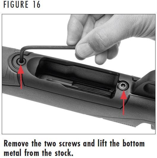
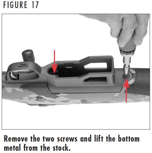
Before adjusting the trigger, you must first remove the bottom metal of the rifle. Identify the bottom metal of your rifle and follow the corresponding instructions in Figure 16 or 17.
ROTARY MAGAZINE MODELS
- Remove the magazine from the rifle by pressing the magazine release button.
- Open the bolt and verify the rifle is unloaded.
- Remove the two screws that retain the bottom metal with a 5/32" (4mm) hex wrench (Figure 16).
- Lift the bottom metal from the stock.
- Adjust the trigger using the instructions found under Trigger Adjustment Procedure on Figure 18 or 19.
- When finished making the adjustment, replace the bottom metal back in the stock and torque the trigger guard screws to 35 in. lb.
PLUS MAGAZINE MODELS
- Remove the magazine from the rifle by pressing the magazine release button.
- Open the bolt and verify the rifle is unloaded.
- Remove the two screws that retain the bottom metal with a 5/32" (4mm) hex wrench (Figure 17).
- Lift the bottom metal from the stock.
- Adjust the trigger using the instructions found under Trigger Adjustment Procedure on Figure 18 or 19.
- When finished making the adjustment, replace the bottom metal back in the stock and torque the trigger guard screws to 35 in. lb.
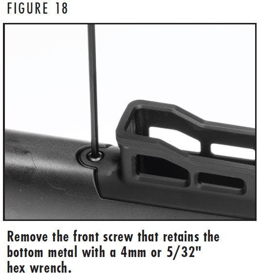
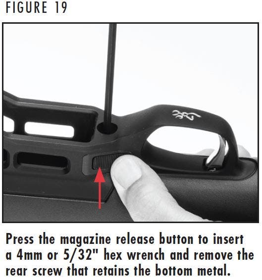
TARGET (AICS MAGAZINE) MODELS
- Remove the magazine from the rifle by pressing the magazine release button. Open the bolt and verify the rifle is unloaded.
- Remove the front screw that retains the bottom metal with a 4mm or 5/32" hex wrench (Figure 18) by turning the screw counterclockwise.
- Push and hold the magazine release button and insert a 4mm or 5/32" (4mm) hex wrench into the hole in the rear of the bottom metal (Figure 19). Turn the screw counterclockwise to remove it. The bottom metal will lift as the rear screw is loosened.
- Remove the bottom metal from the rifle.
- Adjust the trigger using the instructions found on the Trigger Adjustment Procedure on Figure 20.
- When finished making the adjustment, replace the bottom metal back in the stock.
- Install the rear screw first and tighten until it is snug.
- Install the front screw and torque it to 35 in. lb.
- Torque the rear screw to 35 in. lb.
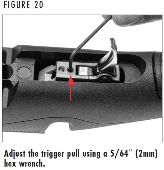
TRIGGER ADJUSTMENT PROCEDURE
- Identify the style of bottom metal on your rifle and remove it from your rifle using the instructions shown above (Either Figure 16, 17, or 18 based on the model).
- Carefully remove the red material from the hole closest to the trigger.
- Adjust the trigger by inserting a 5/64" (2mm) hex wrench into the screw located in front of the trigger (Figure 20).
- To increase the weight of the trigger pull, turn the adjustment screw in a clockwise direction.
- To decrease the weight of the trigger pull, turn the adjustment screw in a counterclockwise direction.
- Trigger pull can be measured, with the rifle unloaded and the bolt closed, using a very accurate spring scale or a commercially available set of trigger pull measuring weights. Most gunsmiths can also measure trigger pull for you.
- When finished making the adjustment, replace the bottom metal following the instructions shown above (Either Figure 16, 17, or 18 based on the model).
WARNING: BEFORE PERFORMING ANY ADJUSTMENTS TO THE COMB HEIGHT OR COMB HARDWARE, ALWAYS PLACE THE “SAFETY” IN THE ON SAFE POSITION. KEEP THE MUZZLE POINTED IN A SAFE DIRECTION AND YOUR FINGERS AWAY FROM THE TRIGGER. FAILURE TO FOLLOW THESE WARNINGS COULD RESULT IN SERIOUS INJURY OR DEATH.
ALWAYS INSPECT THE CHAMBER, BARREL AND MAGAZINE CAREFULLY TO BE SURE ALL LIVE CARTRIDGES ARE CLEARED FROM THE FIREARM.
Composite Stock Adjustment
Composite Stock Adjustment
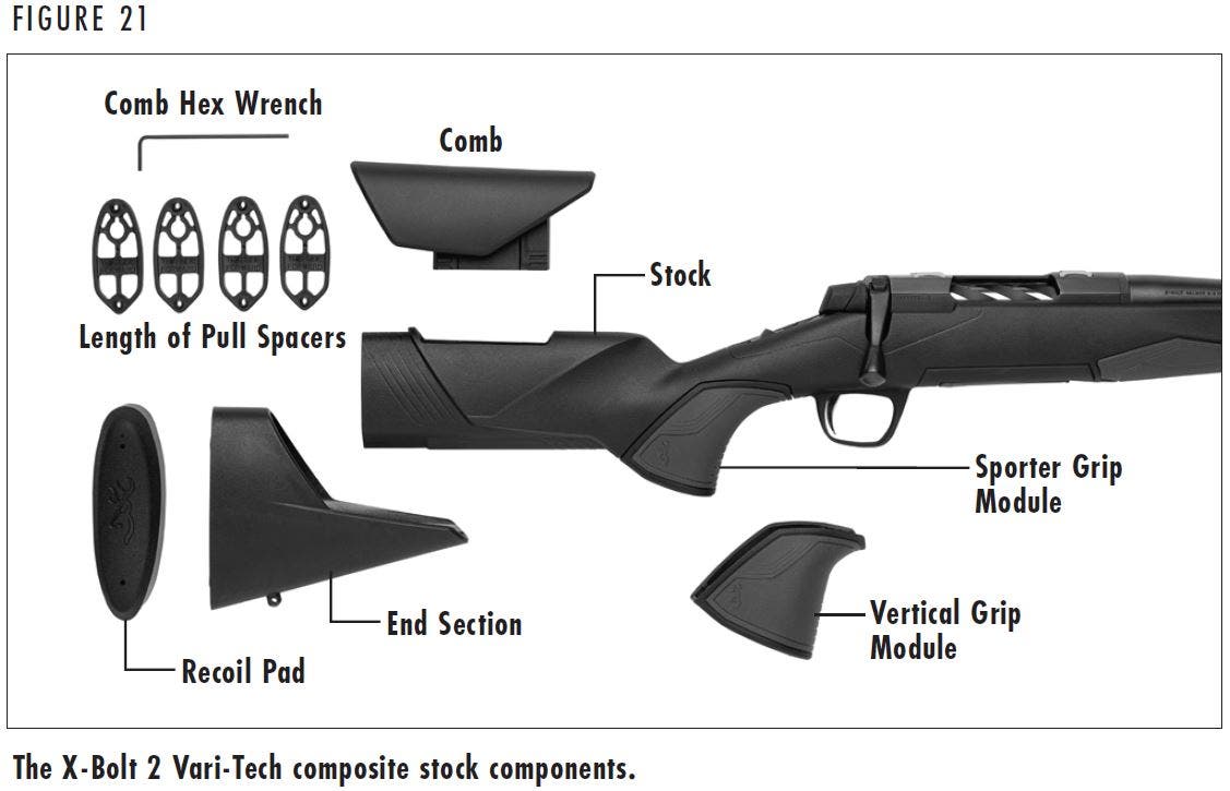
Some X-Bolt 2 rifles feature the Vari-Tech composite stock (Figure 21) with a height adjustable comb to optimize eye-to-scope alignment with optics, length of pull adjustment to accommodate users of different sizes, and include different modules that allow the user to change the angle of the grip.
WARNING: BEFORE PERFORMING ANY ADJUSTMENTS TO THE COMB HEIGHT OR COMB HARDWARE, ALWAYS PLACE THE “SAFETY” IN THE ON SAFE POSITION. KEEP THE MUZZLE POINTED IN A SAFE DIRECTION AND YOUR FINGERS AWAY FROM THE TRIGGER. FAILURE TO FOLLOW THESE WARNINGS COULD RESULT IN SERIOUS INJURY OR DEATH.
ALWAYS INSPECT THE CHAMBER, BARREL AND MAGAZINE CAREFULLY TO BE SURE ALL LIVE CARTRIDGES ARE CLEARED FROM THE FIREARM.
COMB HEIGHT ADJUSTMENT
1. Place the “safety” in the on safe position, open the bolt, and ensure the chamber is unloaded. Remove the magazine.
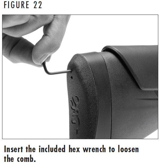
2. Remove the bolt as explained In Figure 6, to help prevent damage to the comb during adjustment.
3. To loosen the comb, locate the smallest hole at the top of the recoil pad (Figure 22). Place a small amount of petroleum jelly on the hole to help prevent damage to the recoil pad.
4. Insert the included 2.5mm hex wrench into the hole. Make certain the tip of the hex wrench engages the head of the screw. Using the wrench, turn the screw counterclockwise approximately 20-25 full turns, until the comb can be slid rearward and raised or lowered in the stock. The comb has six adjustment positions spanning a range of approximately 1" (Figure 23).
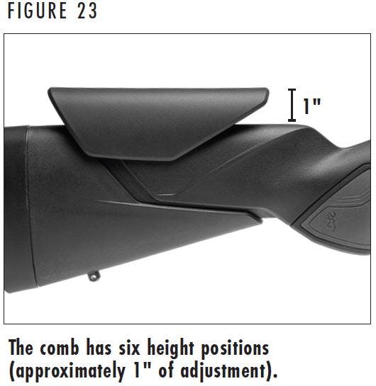

RAISING THE COMB MORE THAN 1" WILL PREVENT THE COMB FROM BEING PROPERLY SECURED TO THE STOCK AND COULD RESULT IN INJURY OR DAMAGE TO THE RIFLE WHEN FIRING.
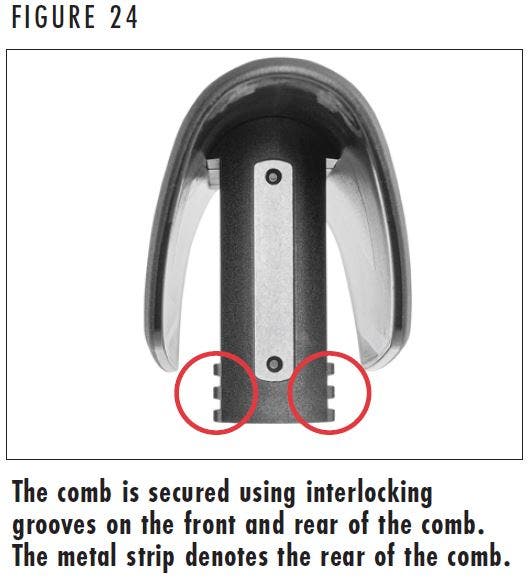
5. Move the comb up or down to the desired position and slide the comb forward to engage the interlocking grooves (Figure 24) located on the front and rear edges of the comb and the stock to temporarily secure it in position. Note that the rear of the comb is denoted by the strip of attached metal. Ensure that the comb is level on the stock by ensuring that the front edge of the comb is parallel with the top of the stock (Figure 25).
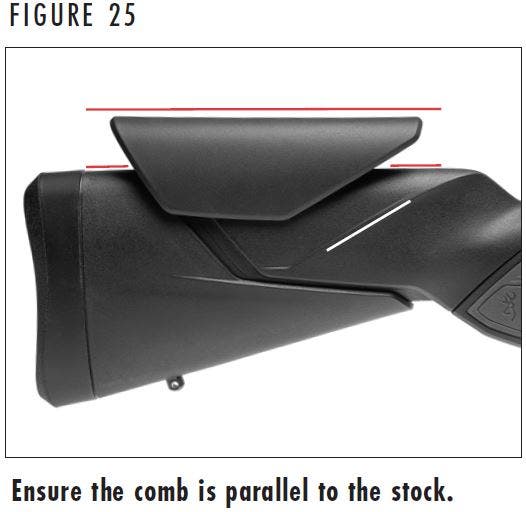
CAUTION: ENSURE THAT THE COMB IS LEVEL WHEN INSTALLING THE COMB. FAILURE TO ENSURE THE COMB IS LEVEL COULD RESULT IN INJURY OR DAMAGE TO THE RIFLE WHEN FIRING.
6. To check comb height, assume your normal shooting position and close your eyes. When you are in a comfortable shooting position, open your eyes. Your scope eye should be in alignment with the scope without shifting the position of your face on the comb. Raise or lower the comb as necessary to achieve correct alignment. Optimal comb height may vary slightly if you are shooting from the bench, prone, etc.
7. Once your eye is aligned with the scope, secure the comb in place by inserting the included 2.5mm hex wrench through the recoil pad into the comb fixing screw and turning the screw clockwise 20-25 full turns until it is secure. Do not overtighten.
WARNING: BEFORE PERFORMING LENGTH OF PULL ADJUSTMENT PROCEDURES, PLACE THE “SAFETY” IN THE ON SAFE POSITION. OPEN THE ACTION AND MAKE CERTAIN YOUR RIFLE IS COMPLETELY UNLOADED. KEEP THE MUZZLE POINTED IN A SAFE DIRECTION. FAILURE TO FOLLOW THESE WARNINGS COULD RESULT IN SERIOUS INJURY OR DEATH.
Length of Pull Adjustment
Length of Pull Adjustment
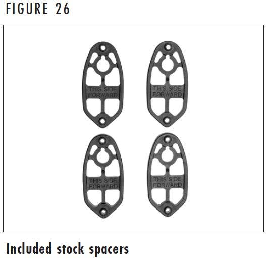
X-Bolt 2 rifles with the Vari-Tech stock are easily adjusted for length of pull by adding or removing spacers to the stock (Figure 26). Four 1/4" spacers are included with rifles that feature this style of stock, allowing for up to 1" of length of pull adjustment.
NOTICE: DO NOT ADD MORE THAN FOUR SPACERS TO LENGTHEN THE PULL OF THIS STYLE OF STOCK. ADDITIONALLY, DO NOT ATTEMPT TO SHORTEN THE LENGTH OF PULL OF THIS RIFLE BEYOND WHAT CAN BE PERFORMED BY REMOVING STOCK SPACERS. DOING SO MAY RESULT IN INJURY OR DAMAGE TO THE RIFLE WHEN FIRING.
1. Install the Allen bolt through the two spacers and the comb riser. Place the nut in the open slot in the comb riser (Figure 16).
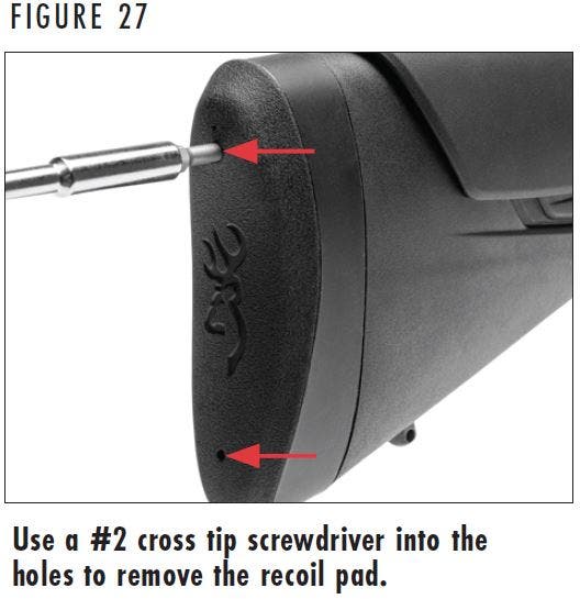
2. To remove the recoil pad, loosen the screws in the two larger holes in the recoil pad (Figure 27). Place a small amount of petroleum jelly on the holes to help prevent damaging the recoil pad.
3. Insert a #2 cross tip screwdriver into one of the holes and make certain the tip of the screwdriver engages the head of the screw. Turn the screw counterclockwise until the screw is completely loose from the stock. Repeat this procedure for the other screw. With both screws loose remove the recoil pad.
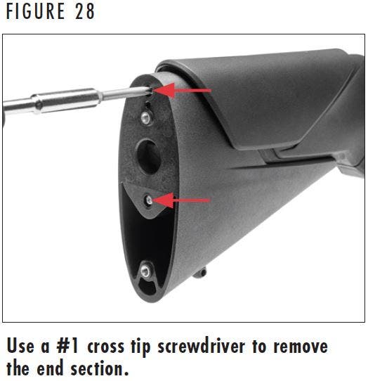
4. Loosen one of the two screws that secures the end section of the stock using a #1 cross tip screwdriver (Figure 28). Turn the screw counterclockwise until it is completely loose from the stock. Repeat this procedure for the other screw. With both screws loose remove the end of the stock by pulling it to the rear.
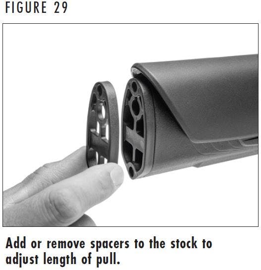
5. Add or subtract spacers to the stock to fit your firearm to your specifications (Figure 29). After making an adjustment, put the recoil pad in place and hold the rifle to your shoulder to determine if the new length feels comfortable. Remember to always keep the “safety” in the on safe position, the muzzle pointed in a safe direction, and make certain the rifle is completely unloaded.
NOTE: The spacers are labeled for correct installation.
6. When satisfied with the length of pull, use a #1 cross tip screwdriver to tighten the screws that secure the butt section to the stock. Turn the screws clockwise and tighten the screws evenly. Do not overtighten.
7. Attach the recoil pad to the stock using the #2 cross tip screwdriver. Turn the screws clockwise to tighten. Do not overtighten.
WARNING: BEFORE CHANGING THE GRIP MODULE, PLACE THE “SAFETY” IN THE ON SAFE POSITION. OPEN THE ACTION AND MAKE CERTAIN YOUR RIFLE IS COMPLETELY UNLOADED. KEEP THE MUZZLE POINTED IN A SAFE DIRECTION. FAILURE TO FOLLOW THESE WARNINGS COULD RESULT IN SERIOUS INJURY OR DEATH.
CHANGING THE GRIP MODULE
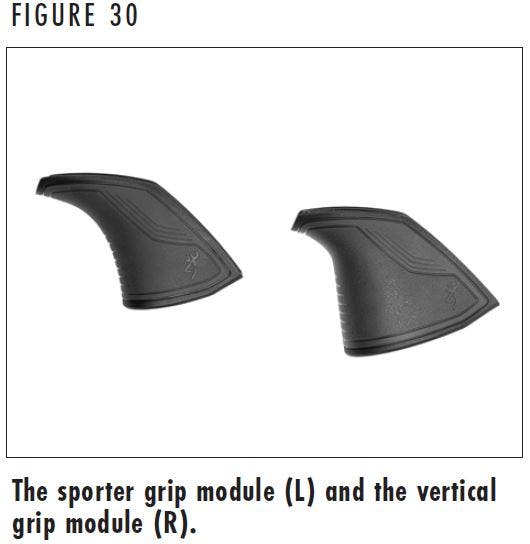
Some X-Bolt 2 rifles with the Vari-Tech composite stock include two grip modules that change the angle of the grip (Figure 30). Many shooters prefer the angled, sporter contour grip for faster finger to trigger reach when hunting, while target shooters opt for the precision finger to trigger placement that the vertical grip provides.
- Place the “safety” in the on safe position, open the bolt, and ensure the chamber is unloaded. Remove the magazine.
- Remove the bottom metal according to the instructions for your rifle shown above (Either Figure 16, 17, or 18 based on the model).
- Carefully remove the barreled action from the stock.
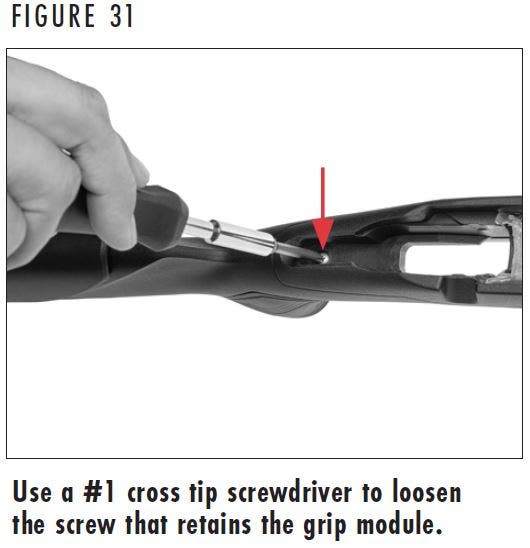
- Locate the screw at the rear of the action channel. Using a #1 cross tip screwdriver (Figure 31), turn the screw counterclockwise until the grip module is loose.
- Remove the grip module from the stock by pulling the front of the grip module down and away from the stock.
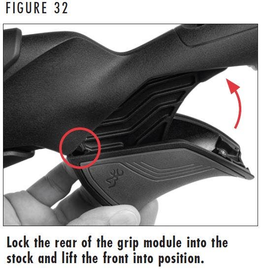
- To install the grip module, lock the rear of the grip module into the stock (Figure 32) and rotate the front of the grip module up and into place on the stock.
- Tighten the grip module screw using a #1 cross tip screwdriver. Do not overtighten.
- Install the barreled action into the stock. Replace the bottom metal in the stock and reinstall the trigger guard screws snugly.
WARNING: BEFORE PERFORMING ANY ADJUSTMENTS TO THE STOCK, ALWAYS PLACE THE “SAFETY” IN THE ON SAFE POSITION. KEEP THE MUZZLE POINTED IN A SAFE DIRECTION AND YOUR FINGERS AWAY FROM THE TRIGGER. FAILURE TO FOLLOW THESE WARNINGS COULD RESULT IN SERIOUS INJURY OR DEATH.
ALWAYS INSPECT THE CHAMBER, BARREL, AND MAGAZINE CAREFULLY TO BE SURE ALL LIVE CARTRIDGES ARE CLEARED FROM THE FIREARM.
Max Stock Adjustment
Max Stock Adjustment
Some X-Bolt 2 rifles feature the Browning MAX stock. This stock features adjustable comb height to optimize eye-to-scope alignment and is also adjustable for length of pull to accommodate users of different sizes.
WARNING: BEFORE PERFORMING ANY ADJUSTMENTS TO THE COMB HEIGHT OR COMB HARDWARE, ALWAYS PLACE THE “SAFETY” IN THE ON SAFE POSITION. KEEP THE MUZZLE POINTED IN A SAFE DIRECTION AND YOUR FINGERS AWAY FROM THE TRIGGER. FAILURE TO FOLLOW THESE WARNINGS COULD RESULT IN SERIOUS INJURY OR DEATH.
ALWAYS INSPECT THE CHAMBER, BARREL, AND MAGAZINE CAREFULLY TO BE SURE ALL LIVE CARTRIDGES ARE CLEARED FROM THE FIREARM.
The MAX stock features a comb that is adjustable for height to optimize eye-to-scope alignment with optics, scope mounts with built-in elevation, or when shooting from different positions.
COMB HEIGHT ADJUSTMENT
- Place the “safety” in the on safe position, open the bolt and ensure the chamber is unloaded. Remove the magazine.
- Remove the bolt as explained in Figure 6 to help prevent damage to the comb during adjustment.
- Loosen the comb. Your rifle may be fitted with either a comb knob or a hex bolt on the side of the stock that secures the comb. Turn the comb knob or use a 5mm hex wrench to turn the hex bolt counterclockwise to loosen the comb.
- Assume your normal shooting position and close your eyes. When you are in a comfortable shooting position, open your eyes. Your scope eye should be in alignment with the scope without shifting the position of your face on the comb. Raise or lower the comb as necessary to achieve correct alignment. Optimal comb height may vary slightly if you are shooting from the bench, prone, etc. Your rifle may have markings on the rear of the comb that allow you to record information for different shooting positions.
- Once your eye is aligned with the scope, secure the comb in place using the comb knob or 5mm hex wrench in the stock by turning it clockwise until it is secure. Do not overtighten.
MOVING THE COMB KNOB TO THE OPPOSITE SIDE OF THE STOCK
Right-handed shooters should have the comb knob on the right side of the stock, left-handed shooters should have the comb knob on the left side of the stock.
CAUTION: INSTALL THE COMB KNOB ON THE CORRECT SIDE OF THE STOCK FOR RIGHT- OR LEFT-HANDED SHOOTERS TO HELP PREVENT THE COMB KNOB FROM CONTACTING THE FACE WHEN FIRING THE RIFLE, WHICH COULD RESULT IN INJURY.
1. Place the “safety” in the on safe position, open the bolt and ensure the chamber is unloaded. Remove the magazine.
2. Remove the bolt as explained on Figure 6 to help prevent damage to the comb during adjustment.
3. Loosen the comb knob by turning it counterclockwise and lower the comb to its lowest position. Secure the comb in place by tightening the comb knob.
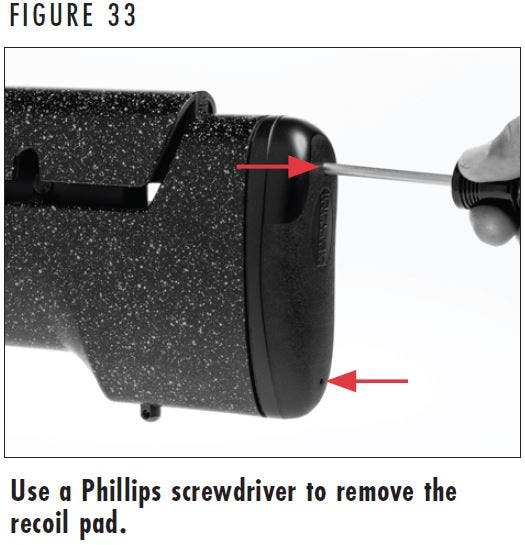
4. Locate two screw access holes in the top and bottom of the recoil pad (Figure 33). Remove the recoil pad using a #2 cross tip or Phillips screwdriver. Place a small amount of petroleum jelly on the holes to help prevent damaging the recoil pad. Insert the screwdriver into the holes and make certain the tip of the screwdriver engages the heads of the screws. Turn the screws counterclockwise until the screws are completely loose from the stock and remove the recoil pad.
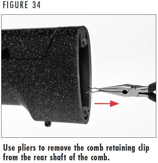
5. With the recoil pad removed, use a flashlight to see into the open end of the stock and locate the comb retaining clip on the rear comb post. Use needle nose pliers to pull the comb retaining clip off the post (Figure 34). With the comb retaining clip removed, loosen and remove the comb knob and lift the comb from the stock.
6. Use a Phillips screwdriver to loosen the two Phillips screws that secure the comb riser to the stock approximately 1/4". Do not remove the Phillips screws.
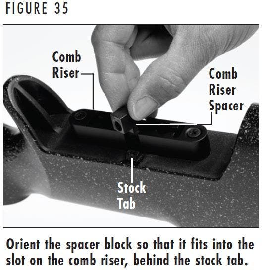
7. Lift the comb riser approximately 1/4" and remove the comb knob bolt and comb riser spacer. Swap these two components to the opposite sides of the comb riser of which they are installed. Ensure the head of the comb knob bolt fits into the slot in the comb riser and the extended tab on the comb riser spacer fit into the recess on the comb riser (Figure 35).
8. Tighten the two Phillips screws that secure the comb riser to the stock to secure the comb riser bolt and comb riser spacer in place on the comb riser. Do not overtighten.
9. Install the comb onto the stock. The numbers on the comb should be to the rear of the stock. Place the comb into the lowest position.
10. Screw the comb knob onto the comb riser bolt and use it to secure the comb in the low position.
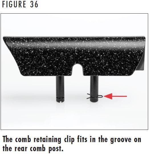
11. Use needle nose pliers to install the comb retaining clip into the groove at the bottom of the rear comb post (Figure 36).
12. Install the recoil pad using a Phillips screwdriver to tighten the two screws. Turn each screw a little at a time to keep the screws inside the recoil pad. Do not overtighten the screws.
ELIMINATING THE COMB KNOB (MAX STOCK ONLY)
Some shooters prefer to remove the comb knob from their rifle and replace it with a hex bolt. A comb knob delete parts kit was included with your rifle to do this. This kit includes one hex bolt, one nut, one rectangular spacer block, one round spacer, and a 5mm hex wrench.
1. Place the “safety” in the on safe position, open the bolt and ensure the chamber is unloaded. Remove the magazine.
2. Remove the bolt as explained in Figure 6 to help prevent damage to the comb during adjustment.
3. Loosen the comb knob by turning it counterclockwise and lower the comb to its lowest position. Secure the comb in place by tightening the comb knob.
4. Locate two screw access holes in the top and bottom of the recoil pad (Figure 33). Remove the recoil pad using a #2 cross tip or Phillips screwdriver. Place a small amount of petroleum jelly on the holes to help prevent damaging the recoil pad. Insert the screwdriver into the holes and make certain the tip of the screwdriver engages the heads of the screws. Turn the screws counterclockwise until the screws are completely loose from the stock and remove the recoil pad.
5. With the recoil pad removed, use a flashlight to look into the open end of the stock and locate the comb retaining clip on the rear comb post. Use needle nose pliers to pull the comb retaining clip off the post (Figure 34). With the comb retaining clip removed, loosen and remove the comb knob and lift the comb from the stock.
6. Use a Phillips screwdriver to loosen the two Phillips screws that secure the comb riser to the stock approximately 1/4". Do not remove the Phillips screws.
7. Lift the comb riser approximately 1/4" and remove the comb knob bolt and comb riser spacer.
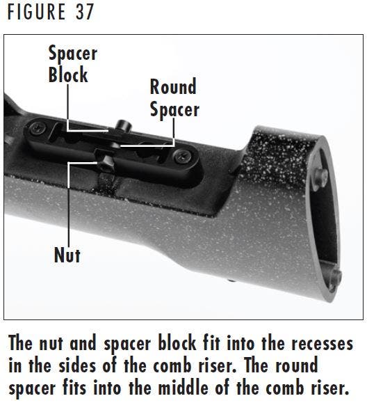
8. Install the comb knob delete kit by first installing the rectangular comb spacer block into one of the slots on the side of the comb riser. Place the round spacer into the opening in the middle of the comb riser.
NOTICE: ENSURE THE ROUND SPACER IS INSTALLED CORRECTLY. INCORRECT INSTALLATION OR OMITTING THE ROUND SPACER COULD RESULT IN DAMAGE TO THE COMB RISER WHEN TIGHTENING THE HEX BOLT.
9. Install the hex bolt through the two spacers and the comb riser. Place the nut in the open slot in the comb riser (Figure 37).
10. Tighten the two Phillips screws that secure the comb riser to the stock. Do not overtighten.
11. Install the comb onto the stock with the numbers on the comb to the rear of the rifle. Place the comb into the lowest position.
12. Snug the 5mm hex bolt to secure the comb in the low position.
13. Use needle nose pliers to install the comb retaining clip into the groove at the bottom of the rear comb post (Figure 36).
14. Install the recoil pad using a Phillips screwdriver to tighten the two screws. Turn each screw a little at a time to keep the screws inside the recoil pad.
15. Adjust the comb as explained under the “Comb Height Adjustment” section.
NOTICE: THE LENGTH OF PULL ADJUSTMENT PROCEDURES FOR X-BOLT 2 MAX STOCKS DIFFER SLIGHTLY FROM EARLIER VERSIONS OF THE MAX STOCK. WHEN ADJUSTING LENGTH OF PULL, PLEASE FOLLOW THE DIRECTIONS OUTLINED IN THIS OWNER’S MANUAL TO PREVENT DAMAGE TO YOUR RIFLE.
Length of Pull Adjustment
Length of Pull Adjustment
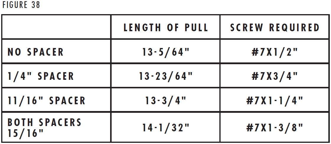
The MAX stock is easily adjusted for length of pull by adding or removing spacers to the rear of the stock. 1/4" and 11/16" size spacers are included with new rifles. The required screws needed to install the different spacers are not included with your rifle. If longer or shorter screws are needed, commonly found #7 pan head, Phillips-style, self tapping wood screws of the necessary length are the recommended replacement screws. Refer to Figure 38 to find the correct length screws required for your application. Spacers can be ordered through your Browning dealer or by calling our Customer Service Department at (800) 322-4626.
NOTE: Browning MAX composite stocks on X-Bolt 2 rifles cannot be shortened.
WARNING: BEFORE PERFORMING ADJUSTMENT PROCEDURES, PLACE THE “SAFETY” IN THE ON SAFE POSITION. OPEN THE ACTION AND MAKE CERTAIN YOUR RIFLE IS COMPLETELY UNLOADED. KEEP THE MUZZLE POINTED IN A SAFE DIRECTION. FAILURE TO FOLLOW THESE WARNINGS COULD RESULT IN SERIOUS INJURY OR DEATH.
ADJUSTING LENGTH OF PULL USING SPACERS
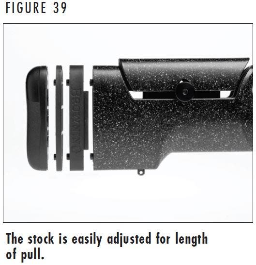
- Locate two screw access holes in the top and bottom of the recoil pad (Figure 33). Remove the recoil pad using a #2 cross tip screwdriver. Place a small amount of petroleum jelly on the holes to help prevent damaging the recoil pad. Insert the screwdriver into the holes and make certain the tip of the screwdriver engages the heads of the screws. Turn the screws counterclockwise until the screws are completely loose from the stock and remove the recoil pad.
- Add or subtract spacers to fit your firearm to your specifications (Figure 39). After making an adjustment, put the recoil pad in place and hold the rifle to your shoulder to determine if the new length feels comfortable. Remember to always keep the muzzle pointed in a safe direction, with the “safety” in the on safe position, and make certain the rifle is completely unloaded.
- When you are satisfied with the length of pull, start the screws through the recoil pad and spacer(s) and into in the stock.
- Attach the recoil pad to the stock using the screwdriver. Turn the screws clockwise to tighten. Do not overtighten the screws.
WARNING: BEFORE ADDING AN EXTENDED RAIL, PLACE THE “SAFETY” IN THE ON SAFE POSITION. OPEN THE ACTION AND MAKE CERTAIN YOUR RIFLE IS COMPLETELY UNLOADED. KEEP THE MUZZLE POINTED IN A SAFE DIRECTION. FAILURE TO FOLLOW THESE WARNINGS COULD RESULT IN SERIOUS INJURY OR DEATH.
Accessory Rail
Accessory Rail
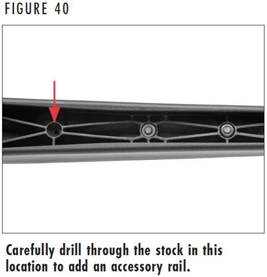
Some X-Bolt 2 rifles with a composite Vari-Tech or MAX stock have an additional second or third, reinforced, blind hole in the fore-end (Figure 40) that can be drilled for an extended Picatinny-style rail or ARCA/Swiss rail.
1. Place the “safety” in the on safe position, open the bolt, and ensure the chamber is unloaded. Remove the magazine.
2. Remove the bottom metal according to the instructions for your rifle (Either Figure 16, 17, or 18 based on the model)..
3. Carefully remove the barreled action from the stock.
4. Locate the blind hole toward the rear of the fore-end (Figure 40). Carefully drill through the stock using a 13/64" drill bit.
5. Insert a 10-32 threaded nut insert, GrovTec part 490221 or similar, inside the stock into the second or third hole and carefully install the accessory rail. As the screw is tightened, it will pull the fastener into position in the stock and secure it in place.
NOTICE: DO NOT OVERTIGHTEN THE SCREW. YOU MAY DAMAGE THE STOCK OR ACCESSORY RAIL.
NOTICE: MAKE SURE THAT THE FASTENER DOES NOT EXTEND INTO THE BARREL CHANNEL AND MAKE CONTACT WITH THE BARREL WHEN INSTALLED.
6. Finish installing the rail following the manufacturer’s instructions.
WARNING: THE ADDITION OF A RECOIL REDUCING MUZZLE BRAKE SIGNIFICANTLY INCREASES NOISE AND MUZZLE BLAST. YOU, AND EVERYONE IN CLOSE PROXIMITY TO THE FIREARM, SHOULD ALWAYS WEAR HEARING PROTECTION TO HELP PREVENT HEARING LOSS OR DAMAGE AND SAFETY GLASSES TO HELP PREVENT DEBRIS FROM INJURING THE EYES.
WHEN USING A SUPPRESSOR, ALWAYS WEAR HEARING AND EYE PROTECTION. EVEN THOUGH SOUND IS REDUCED WHEN USING A SUPPRESSOR, THE NOISE LEVELS ARE STILL SIGNIFICANT ENOUGH TO CAUSE PERMANENT HEARING LOSS. BE AWARE THAT USING A SUPPRESSOR INCREASES THE BACK PRESSURE IN THE BARREL WHEN A CARTRIDGE IS FIRED. THE INCREASE IN BACK PRESSURE MAY CAUSE DEBRIS FROM THE CARTRIDGE TO EXIT THE EJECTION PORT OF THE FIREARM AND CONTACT YOUR EYES, EARS AND FACE, OR THOSE OF ANYONE IN CLOSE PROXIMITY TO THE FIREARM. THE INCREASE IN BACK PRESSURE MAY ALSO RESULT IN THE DEPOSIT OF ADDITIONAL DEBRIS IN YOUR FIREARM; ACCORDINGLY, AN ACCELERATED CLEANING SCHEDULE FOR YOUR FIREARM MAY BE NECESSARY.
ENSURE THAT ANY MUZZLE BRAKE OR SUPPRESSOR THAT YOU INTEND TO USE ON YOUR FIREARM IS DESIGNED FOR USE WITH YOUR FIREARM’S CALIBER. NEVER USE A MUZZLE BRAKE OR SUPPRESSOR THAT IS DESIGNED FOR RIMFIRE USE ONLY ON A CENTERFIRE FIREARM. BEFORE INSTALLING OR REMOVING A MUZZLE BRAKE OR SUPPRESSOR TO/FROM YOUR FIREARM, READ THIS OWNER’S MANUAL AND ANY OWNER’S MANUAL INCLUDED WITH THE DEVICE, AND PRECISELY FOLLOW ALL INSTALLATION AND MAINTENANCE INSTRUCTIONS PROVIDED BY THE SUPPRESSOR OR MUZZLE BRAKE MANUFACTURER. DURING INSTALLATION OR REMOVAL, ALWAYS KEEP THE MUZZLE POINTED IN A SAFE DIRECTION AND MAKE CERTAIN THAT THE FIREARM IS COMPLETELY UNLOADED, WITH THE MAGAZINE REMOVED AND THE ACTION IN THE OPEN POSITION.
PERIODICALLY CHECK THE MUZZLE BRAKE OR SUPPRESSOR TO ENSURE THAT IT IS TIGHT AND FIRMLY SEATED. BEFORE CHECKING, FOLLOW ALL SAFETY GUIDELINES PREVIOUSLY OUTLINED. ENSURE THE MUZZLE BRAKE OR SUPPRESSOR IS COOL BEFORE TOUCHING IT.
FAILURE TO FOLLOW THESE WARNINGS MAY RESULT IN INJURY OR DEATH TO YOU OR THOSE AROUND YOU!
Muzzle Brakes and Suppressors
Muzzle Brakes and Suppressors
Most Browning rifles equipped with a muzzle brake also include a thread protector that can be installed in place of the muzzle brake. Whether using the thread protector, muzzle brake or suppressor, be aware that your firearm’s point of impact may change as the harmonics of the barrel are affected when changing the weight at the end of the barrel.
WARNING: READ AND PRECISELY FOLLOW ALL INSTALLATION AND MAINTENANCE INSTRUCTIONS CONTAINED IN THIS OWNER’S MANUAL BEFORE INSTALLING OR REMOVING THE RECOIL HAWG MUZZLE BRAKE. PLACE THE “SAFETY” OF YOUR RIFLE IN THE ON SAFE POSITION. REMOVE THE MAGAZINE, OPEN THE ACTION, AND MAKE CERTAIN YOUR RIFLE IS COMPLETELY UNLOADED. ALWAYS KEEP THE MUZZLE POINTED IN A SAFE DIRECTION. FAILURE TO FOLLOW THESE WARNINGS COULD RESULT IN SERIOUS INJURY OR DEATH TO YOU OR THOSE AROUND YOU!
PERIODICALLY CHECK THE MUZZLE BRAKE TO ENSURE THAT IT IS TIGHT AND FIRMLY SEATED. BEFORE CHECKING, FOLLOW ALL SAFETY GUIDELINES PREVIOUSLY OUTLINED. TO PREVENT BURNS, ENSURE THE MUZZLE BRAKE IS COOL BEFORE TOUCHING IT. FAILURE TO FOLLOW THESE WARNINGS COULD RESULT IN SERIOUS INJURY OR DEATH TO YOU OR THOSE AROUND YOU!
THE ADDITION OF A RECOIL REDUCING MUZZLE BRAKE SIGNIFICANTLY INCREASES NOISE AND MUZZLE BLAST. YOU, AND EVERYONE IN CLOSE PROXIMITY TO THE FIREARM, SHOULD ALWAYS WEAR HEARING PROTECTION TO HELP PREVENT HEARING LOSS OR DAMAGE AND SAFETY GLASSES TO HELP PREVENT DEBRIS FROM INJURING THE EYES.
DISCHARGING FIREARMS IN POORLY VENTILATED AREAS, CLEANING FIREARMS, OR HANDLING AMMUNITION MAY RESULT IN EXPOSURE TO LEAD AND OTHER SUBSTANCES KNOWN TO CAUSE BIRTH DEFECTS, REPRODUCTIVE HARM, AND OTHER SERIOUS PHYSICAL INJURY. HAVE ADEQUATE VENTILATION AT ALL TIMES. WASH HANDS THOROUGHLY AFTER EXPOSURE.
WEAR EYE PROTECTION WHEN INSTALLING OR REMOVING THE RECOIL HAWG, OR OTHER OBJECT FROM YOUR RIFLE, OR CLEANING YOUR RIFLE TO KEEP PARTS, SOLVENTS, OR OTHER AGENTS FROM CONTACTING YOUR EYES, RESULTING IN INJURY.
NOTICE: BE AWARE THAT YOUR RIFLE’S POINT OF IMPACT MAY CHANGE AS THE HARMONICS OF THE BARREL ARE AFFECTED WHEN ADDING A MUZZLE BRAKE, WHICH CHANGES THE WEIGHT AT THE END OF THE BARREL.
RECOIL HAWG MUZZLE BRAKES
DESCRIPTION
The Recoil Hawg muzzle brake is designed to reduce felt recoil by as much as 76% (depending on caliber). Not only does the Recoil Hawg increase shooting comfort, it reduces muzzle rise and dust signature, making it easier to spot target impacts.
WARNING: BEFORE REMOVING THE RECOIL HAWG, PLACE THE “SAFETY” IN THE ON SAFE POSITION. REMOVE THE MAGAZINE, OPEN THE ACTION, AND MAKE CERTAIN YOUR RIFLE IS COMPLETELY UNLOADED. KEEP THE MUZZLE POINTED IN A SAFE DIRECTION. FAILURE TO FOLLOW THESE WARNINGS COULD RESULT IN SERIOUS INJURY OR DEATH.
REMOVAL
The Recoil Hawg is easily removed for cleaning or to install a thread protector or other accessory.
- Place your rifle in a gun vise, on a table, or other safe / secure location with the top of the receiver upward. Protect the finish with rags or other padding.
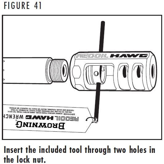
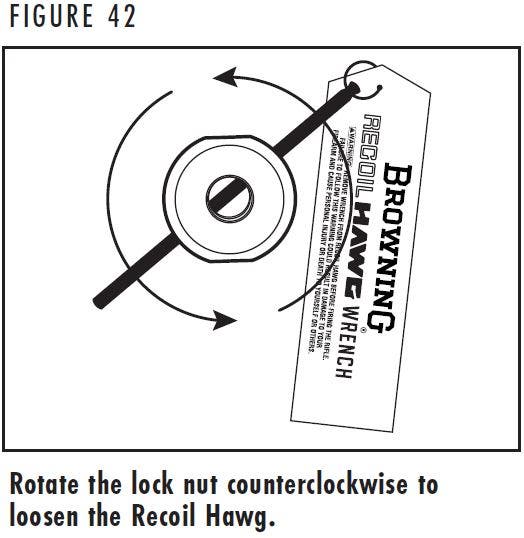
- Insert the included tool through two holes in the lock nut (Figure 41) and turn the installation tool counterclockwise until the lock nut is free from the barrel (Figure 42).
- Remove the lock nut and Recoil Hawg.
WARNING: BEFORE INSTALLING THE RECOIL HAWG, PLACE THE “SAFETY” IN THE ON SAFE POSITION. REMOVE THE MAGAZINE, OPEN THE ACTION, AND MAKE CERTAIN YOUR RIFLE IS COMPLETELY UNLOADED. KEEP THE MUZZLE POINTED IN A SAFE DIRECTION. FAILURE TO FOLLOW THESE WARNINGS COULD RESULT IN SERIOUS INJURY OR DEATH.
INSTALLATION
- Place your rifle in a gun vise, on a table, or other safe / secure location with the top of the receiver upward. Protect the finish with rags or other padding.
- Remove any muzzle brake, thread protector, or other object from the threaded end of the barrel according to the manufacturer’s instructions.
- Clean the threads at the muzzle with a gun cleaning solvent and lightly oil the threads.
- Insert the lock nut (holes toward the front of the rifle) into the Recoil Hawg.
- Place the Recoil Hawg and lock nut over the muzzle threads with the logo facing up.
- Turn the lock nut clockwise to thread the lock nut onto the barrel. Ensure that the Recoil Hawg logo is facing up.
- Insert the installation tool through two holes in the lock nut as shown in Figure 41 with half of the tool protruding from each side of the lock nut. To help prevent overtightening the lock nut, grip each end of the installation tool with only your hands and turn clockwise.
WARNING: BEFORE TUNING THE COMPETITION RECOIL HAWG, PLACE THE “SAFETY” IN THE ON SAFE POSITION. REMOVE THE MAGAZINE, OPEN THE ACTION, AND MAKE CERTAIN YOUR RIFLE IS COMPLETELY UNLOADED. KEEP THE MUZZLE POINTED IN A SAFE DIRECTION. FAILURE TO FOLLOW THESE WARNINGS COULD RESULT IN SERIOUS INJURY OR DEATH.
COMPETITION MODEL
The Competition Recoil Hawg has a compensator feature that allows you to customize muzzle rise mitigation. Four ports, sealed with screws, run along the top of the brake. The screws can be removed individually to tune the amount of muzzle rise when firing. With the screw(s) removed, muzzle blast is directed through the open port(s). The escaping muzzle blast creates a downward force that acts upon the muzzle to reduce muzzle jump, help you to spot bullet trace, impacts on the target, and misses in your scope. This data results in easier target adjustments and faster, more accurate follow-up shots.
- At a range or other suitable target shooting location, with your rifle completely unloaded, use the included 3/32" (2.5mm) hex wrench to remove one of the screws from the top of the Competition Recoil Hawg.
- Fire a round at a target. If you are able to watch bullet trace and impact, your rifle is stabilized. However, you may also experiment by removing additional screws from the brake.
- When satisfied with the performance, note the number and positions of the open ports as additional tuning to accommodate different loads may be required.
NOTICE: USE ONLY THE SCREWS PROVIDED WITH THE COMPETITION MUZZLE BRAKE. USING SCREWS THAT ARE TOO LONG COULD RESULT IN DAMAGE TO THE MUZZLE BRAKE.
WARNING: BEFORE PERFORMING CLEANING PROCEDURES, PLACE THE “SAFETY” IN THE ON SAFE POSITION. OPEN THE ACTION AND MAKE CERTAIN YOUR RIFLE IS COMPLETELY UNLOADED. KEEP THE MUZZLE POINTED IN A SAFE DIRECTION. FAILURE TO FOLLOW THESE WARNINGS COULD RESULT IN SERIOUS INJURY OR DEATH.
WEAR EYE PROTECTION WHEN DISASSEMBLING AND CLEANING YOUR RIFLE TO PREVENT THE POSSIBILITY OF SPRINGS, SPRING-TENSIONED PARTS, SOLVENTS OR OTHER AGENTS FROM CONTACTING YOUR EYES, RESULTING IN INJURY.
KEEP ALL AMMUNITION AWAY FROM THE CLEANING AREA. NEVER TEST THE MECHANICAL FUNCTION OF YOUR RIFLE WITH LIVE AMMUNITION. FAILURE TO FOLLOW THESE WARNINGS COULD RESULT IN SERIOUS INJURY OR DEATH.
NOTICE: SOME CLEANING SOLVENTS, LUBRICANTS AND OTHER STRONG CHEMICALS SUCH AS THOSE FOUND IN INSECT REPELLENTS, SUNSCREENS, ETC. MAY DAMAGE THE FINISHES OF YOUR FIREARM. USE CARE TO PREVENT CHEMICALS FROM MAKING CONTACT WITH FINISHES WHEN CLEANING YOUR FIREARM.
Cleaning and Maintenance Suggestions
Cleaning and Maintenance Suggestions
CLEANING PROCEDURES
Your X-Bolt 2 rifle will function better and more reliably over a longer period of time if it is properly maintained and kept clean. Clean your firearm after every day of shooting, and more often if it becomes excessively dirty. A minimum cleaning includes wiping down the firearm and oiling key parts. Regular maintenance will also include cleaning the barrel.
If you encounter a function problem be sure to give your firearm a thorough cleaning to see if it solves the problem before seeking the services of a Browning Recommended Service Center or our Service Facility in Arnold, Missouri, or a qualified gunsmith.
1. Remove the bolt as explained previously.
2. Inspect the chamber and bore for powder fouling. A normal amount of powder residue can be expected and is not serious. It can usually be removed with a patch saturated with nitro solvent. Clean the bore using an appropriate rifle cleaning rod with a tip and patch of the correct caliber to provide a snug fit in the bore. Insert the rod and patch into the barrel at the breech end and run it back and forth several times. Care should be exercised to ensure that the cleaning rod does not strike the crown of the muzzle, as damage to this area can affect the accuracy of your rifle. If, or when, fouling should become heavy, it can be removed with a brass bore brush. Dip or spray the brush with nitro solvent and scrub the chamber and bore until the fouling is removed. To prevent brass bristles from breaking off, the brush should be pushed completely through the barrel before being withdrawn.
To maintain the utmost accuracy of your rifle it is recommended you clean the bore with a copper solvent. Modern bullet jackets are made mainly of copper. Residues from copper bullet jackets stick to the barrel and require more frequent cleaning. Magnum calibers will require more frequent inspection and cleaning. Swab the bore of your rifle with a good copper solvent using the manufacturer’s recommended procedure.
Browning offers a complete line of products to make cleaning your firearm fast and easy. Be sure to follow all instructions when using any product to clean your firearm.
3. After all fouling has been removed, the chamber and bore should be wiped dry. When the bore is dry, pass a slightly oiled patch through it for preservation. A fine, light gun oil is recommended.
4. Inspect the barrel and chamber to be certain no patches have inadvertently been left in them. Remove any that remain.
5. Use a small brush or rag to remove dirt or other foreign matter from inside the receiver and other parts of the action. Lightly lubricate all moving parts with a high-quality, light gun oil. Use oil sparingly, a very light film is sufficient. A fine, light gun oil is ideally suited for this purpose.
NOTICE: DO NOT POUR LARGE QUANTITIES OF OIL INTO THE RECEIVER OR OTHER PARTS. IT CAN DRAIN DOWN TO THE WOOD AND SOFTEN IT, CAUSING PERMANENT DAMAGE AND LOOSENING OF THE STOCK.
6. Wipe all exposed metal surfaces with a lightly oiled cloth making certain that all finger marks are removed. Finger marks provide a place where moisture can accumulate. The metal of the gun should receive a light film of oil any time the rifle has been exposed to weather or handling.
7. Wood surfaces can also be wiped with a quality, lightweight gun oil or they can be polished with any quality furniture wax (but not both).
CLEANING THE MAGAZINE
It is not recommended that the X-Bolt 2 magazine be disassembled. Frequently inspect magazines to determine the need for cleaning as lubricant and dirt will gradually collect in the mechanism. Normally, the magazine should be cleaned after firing 500 to 1,000 cartridges.
NOTICE: DO NOT TAMPER WITH THE ASSEMBLY SCREW ON THE REAR OF THE MAGAZINE. DOING SO WILL RENDER THE MAGAZINE INOPERATIVE.
- Clean the magazine by spraying it with a gun cleaning solvent that will not adversely affect the polymer magazine or corrode the metal components. Spray the magazine with this solvent, both inside and out, to loosen debris.
- Place your finger over the loading port and shake it vigorously (with the loading port away from you) to remove solvent and residue from the magazine.
- Use compressed air to dry the magazine or allow it to air dry.
NOTICE: NEVER ATTEMPT TO TAKE YOUR FIREARM APART FURTHER THAN EXPLAINED IN THIS OWNER’S MANUAL. YOUR FIREARM IS A SPECIALIZED, FINELY FITTED MECHANISM. YOU MAY PERMANENTLY DAMAGE IT BY ATTEMPTING TO DISASSEMBLE THE INNER MECHANISM ASSEMBLIES. IF FURTHER DISASSEMBLY FOR SERVICE OR CLEANING IS REQUIRED, TAKE YOUR FIREARM TO A QUALIFIED GUNSMITH, OR CONTACT OUR ARNOLD, MISSOURI SERVICE FACILITY AS EXPLAINED UNDER THE “SERVICE OR REPAIR” SECTION.
Maintenance of Oil Finish Stocks
Maintenance of Oil Finish Stocks
Keeping the oil-finished wood surfaces on your firearm looking their best requires only a small amount of maintenance. When the surfaces become spotted or dull, the affected area(s) can be treated using rubbing alcohol on a soft, lint free cloth and allowed to dry. A small amount of a linseed oil-based finish, such as Watco® Danish Oil Finish, Deft® Danish Oil Finish, or Formby’s® Tung Oil Finish should then be applied to the surface of the wood with a soft, lint free cloth according to the manufacturers’ instructions. To treat the checkering, a small amount of oil-based finish can be applied and then distributed evenly using a toothbrush or other soft bristled brush.
Models with Special Finishes
Models with Special Finishes
As with any gun, the only way to preserve its pristine condition and collector appeal is to never handle or fire it, which in turn would deprive you of much of the enjoyment that comes with owning a fine Browning firearm.
While special finishes such as engraving and gold plating greatly enhance the aesthetic appeal of your rifle, please be aware that they are no more durable, and in some cases may even be slightly less durable than more common gun finishes.
As you use your Browning rifle, you can expect special finishes to wear in much the same manner as any other firearm finish. These marks are the honest product of the hours spent enjoying your firearm and each scuff and scratch will probably have a good story to go along with it.
SERVICE OR REPAIR
SERVICE OR REPAIR
If your firearm should require service or repairs, we suggest you first contact a local recommended Browning Firearms Service Center.
To locate a service center visit browning.com, contact our Customer Service Department or your Browning firearms dealer for the address of the Service Center nearest you. Otherwise, you may send your firearm directly to our Service Department in Arnold, Missouri.
Parts listings, Firearm Service Center lists, service procedures, service/repair form and general product information are also found on the internet at browning.com. For technical questions about your firearm or service, contact:
United States customers contact:
Browning Firearm Status and
Technical Service
3005 Arnold Tenbrook Rd
Arnold, MO 63010-9406
Phone: (800) 322-4626
Canadian customers contact:
Browning Canada Sports Ltd/Ltée
5583 Chemin St-François
St-Laurent, Quebec H4S 1W6
Phone: (514) 333-7261
When returning your firearm for servicing, you must do the following:
1. Be sure it is completely unloaded.
2. Remove any optics, optic mounts or other accessories.
3. Package it securely in a cardboard container.
4. Enclose the service/repair form available at browning.com or a letter that clearly describes the trouble experienced, the ammunition used and the repairs desired. Also include your name, e-mail address (if possible) and a daytime phone number where you can be reached.
5. Never return ammunition with your firearm. It is against postal and most commerce regulations.
CERTAIN STATES REQUIRE, BY LAW, THAT THEIR OWN SPECIFIED WARNING NOTICES BE INCLUDED BY THE MANUFACTURER, DISTRIBUTOR, OR RETAIL DEALER WITH FIREARMS SOLD IN THAT STATE. BROWNING SELLS ITS PRODUCTS IN COMPLIANCE WITH APPLICABLE LAWS AND REGULATIONS. BECAUSE OUR PRODUCTS MAY BE SOLD IN THESE STATES, WE INCLUDE THE FOLLOWING:
State-By-State Warnings
State-By-State Warnings

CALIFORNIA
Firearms must be handled responsibly and securely stored to prevent access by children and other unauthorized users. California has strict laws pertaining to firearms, and you may be fined or imprisoned if you fail to comply with them. Visit the Website of the California Attorney General at https://oag.ca.gov/firearms for information on firearm laws applicable to you and how you can comply.
Prevent child access by always keeping guns locked away and unloaded when not in use. If you keep a loaded firearm where a child obtains and improperly uses it, you may be fined or sent to prison.
If you or someone you know is contemplating suicide, please call the National Suicide Prevention Lifeline at 1-800-273-TALK (8255).

Las armas de fuego deben de ser manipuladas responsablemente y almacenadas en sitios seguros para prevenir el acceso a ellas por parte de niños y personas sin autorización. California cuenta con leyes estrictas sobre las armas de fuego, y puede ser multado y encarcelado si no las obedece. Visite la página web de California Attorney General, https://oag.ca.gov/firearms para más información sobre cómo cumplir con las leyes de armas de fuego.
Prevenga el acceso de los niños a las armas de fuego manteniéndolas siempre en un lugar seguro, bajo llave y descargadas cuando no estén en uso. Si usted deja un arma cargada al alcance de un niño, y éste la utiliza indebidamente,usted podría ser multado e incluso enviado a la cárcel.
Si usted o alguien que conoce está pensando en suicidarse, llame a la línea Nacional de Prevención del Suicidio al 1-800-273-TALK (8255).
CONNECTICUT
“UNLAWFUL STORAGE OF A LOADED FIREARM MAY RESULT IN IMPRISONMENT OR FINE.”
FLORIDA
“IT IS UNLAWFUL, AND PUNISHABLE BY IMPRISONMENT AND FINE, FOR ANY ADULT TO STORE OR LEAVE A FIREARM IN ANY PLACE WITHIN THE REACH OR EASY ACCESS OF A MINOR UNDER 18 YEARS OF AGE OR TO KNOWINGLY SELL OR OTHERWISE TRANSFER OWNERSHIP OR POSSESSION OF A FIREARM TO A MINOR OR A PERSON OF UNSOUND MIND.”
MAINE
“ENDANGERING THE WELFARE OF A CHILD IS A CRIME. IF YOU LEAVE A FIREARM AND AMMUNITION WITHIN EASY ACCESS OF A CHILD, YOU MAY BE SUBJECT TO FINE, IMPRISONMENT OR BOTH. KEEP FIREARMS AND AMMUNITION SEPARATE. KEEP FIREARMS AND AMMUNITION LOCKED UP. USE TRIGGER LOCKS.”
MARYLAND
“WARNING: Children can operate firearms which may cause death or serious injury. It is a crime to store or leave a loaded firearm in any location where an individual knew or should have known that an unsupervised minor would gain access to the firearm. Store your firearm responsibly!”
MASSACHUSETTS
“WARNING FROM THE MASSACHUSETTS ATTORNEY GENERAL: This handgun is not equipped with a device that fully blocks use by unauthorized users. More than 200,000 firearms like this one are stolen from their owners every year in the United States. In addition, there are more than a thousand suicides each year by younger children and teenagers who get access to firearms. Hundreds more die from accidental discharge. It is likely that many more children sustain serious wounds, or inflict such wounds accidentally on others. In order to limit the chance of such misuse, it is imperative that you keep this weapon locked in a secure place and take other steps necessary to limit the possibility of theft or accident. Failure to take reasonable preventative steps may result in innocent lives being lost, and in some circumstances may result in your liability for these deaths.”
“IT IS UNLAWFUL TO STORE OR KEEP A FIREARM, RIFLE, SHOTGUN OR MACHINE GUN IN ANY PLACE UNLESS THAT WEAPON IS EQUIPPED WITH A TAMPER RESISTANT SAFETY DEVICE OR IS STORED OR KEPT IN A SECURELY LOCKED CONTAINER.”
NEW JERSEY
“IT IS A CRIMINAL OFFENSE TO LEAVE A LOADED FIREARM WITHIN EASY ACCESS OF A MINOR.”
NEW YORK CITY, NEW YORK
“THE USE OF A LOCKING DEVICE OR SAFETY LOCK IS ONLY ONE ASPECT OF RESPONSIBLE WEAPON STORAGE. ALL WEAPONS SHOULD BE STORED UNLOADED AND LOCKED IN A LOCATION THAT IS BOTH SEPARATE FROM THEIR AMMUNITION AND INACCESSIBLE TO CHILDREN AND ANY OTHER UNAUTHORIZED PERSONS. NEW YORK CITY LAW PROHIBITS, WITH CERTAIN EXCEPTIONS, ANY PERSON FROM ACQUIRING MORE THAN ONE FIREARM, OR MORE THAN ONE RIFLE OR SHOTGUN, WITHIN A 90-DAY PERIOD.”
NORTH CAROLINA
“IT IS UNLAWFUL TO STORE OR LEAVE A FIREARM THAT CAN BE DISCHARGED IN A MANNER THAT A REASONABLE PERSON SHOULD KNOW IS ACCESSIBLE TO A MINOR.”
Any person who resides in the same premises as a minor, owns or possesses a firearm, and stores or leaves the firearm (i) in a condition that the firearm can be discharged and (ii) in a manner that the person knew or should have known that an unsupervised minor would be able to gain access to the firearm, is guilty of a Class 1 misdemeanor if a minor gains access to the firearm without the lawful permission of the minor’s parents or a person having charge of the minor and the minor:
- Possesses it in violation of G.S. 14-269.2(b)
- Exhibits it in a public place in a careless, angry, or threatening manner;
- Causes personal injury or death with it not in self defense; or
- Uses it in the commission of a crime.
TEXAS
“IT IS UNLAWFUL TO STORE, TRANSPORT, OR ABANDON AN UNSECURED FIREARM IN A PLACE WHERE CHILDREN ARE LIKELY TO BE AND CAN OBTAIN ACCESS TO THE FIREARM.”
WISCONSIN
“IF YOU LEAVE A LOADED FIREARM WITHIN THE REACH OR EASY ACCESS OF A CHILD YOU MAY BE FINED OR IMPRISONED OR BOTH IF THE CHILD IMPROPERLY DISCHARGES, POSSESSES, OR EXHIBITS THE FIREARM.”
PLEASE CONSULT YOUR LOCAL FEDERALLY LICENSED FIREARMS RETAILER, STATE POLICE, OR LOCAL POLICE FOR ADDITIONAL WARNINGS THAT MAY BE REQUIRED BY LOCAL LAW OR REGULATION. FIREARMS REGULATIONS CHANGE CONSTANTLY AND YOUR LOCAL AUTHORITIES ARE THE BEST SOURCE FOR THE MOST CURRENT INFORMATION ON SUCH LEGAL MATTERS.
BROWNING.COM
US: Morgan, Utah 84050-9326
CANADA: Browning Canada Sports Ltd/Ltée, St-Laurent, Quebec H4S 1W6
INTL: Parc Industriel des Hauts-Sarts, B-4040 Herstal, Belgium