

Browning BT-99 Shotgun Owner's Manual
Browning BT-99 Shotgun Owner's Manual
Important operating instructions for: Browning BT-99 Shotgun.
If you have any questions about your new firearm, this owner’s manual or other Browning products, contact:
Browning Consumer Information
One Browning Place
Morgan, UT 84050-9326
Phone: (800) 333-3288
browning.com
Please use the space below to record information about your new firearm.
Model __________________________________________________
Serial Number ____________________________________________
Purchased From __________________________________________
Date of Purchase __________________________________________
THANK YOU FOR CHOOSING BROWNING
The BT-99 has a proven performance record and a well earned reputation for dependability. Its high quality craftsmanship and function is sure to provide you with a keen sense of confidence in the heat of competition.
With a reasonable amount of care, your BT-99 should give you many years of dependable, enjoyable service.
Specifications within this owner’s manual are correct at the time of printing and subject to change without notice.
STATE WARNING
According to state law, California requires that firearm manufacturers, distributors and retailers include conspicuous, specific warnings with firearms sold in that state.

Firearms must be handled responsibly and securely stored to prevent access by children and other unauthorized users.
California has strict laws pertaining to firearms, and you may be fined or imprisoned if you fail to comply with them. Visit the Web site of the California Attorney General at https://oag.ca.gov/firearms for information on firearm laws applicable to you and how you can comply.
Prevent child access by always keeping guns locked away and unloaded when not in use. If you keep a loaded firearm where a child obtains and improperly uses it, you may be fined or sent to prison.

Las armas de fuego deben de ser manipuladas responsablemente y almacenadas en sitios seguros para prevenir el acceso a ellas por parte de niños y personas sin autorización.
California cuenta con leyes estrictas sobre las armas de fuego, y puede ser multado y encarcelado si no las obedece. Visite la página web de California Attorney General, https://oag.ca.gov/firearms para más información sobre cómo cumplir con las leyes de armas de fuego.
Prevenga el acceso de los niños a las armas de fuego manteniéndolas siempre en un lugar seguro, bajo llave y descargadas cuando no estén en uso. Si usted deja un arma cargada al alcance de un niño, y éste la utiliza indebidamente,usted podría ser multado e incluso enviado a la cárcel.
WARNING: YOU ARE RESPONSIBLE FOR FIREARMS SAFETY
WARNING: YOU ARE RESPONSIBLE FOR FIREARMS SAFETY

FAILURE TO FOLLOW ANY OF THE FOLLOWING WARNINGS COULD RESULT IN SERIOUS INJURY OR DEATH.
As a gun owner, you accept a set of demanding responsibilities. How seriously you take these responsibilities can be the difference between life and death.
There is no excuse for careless or abusive handling of any firearm. At all times handle this firearm and all other firearms with intense respect for their power and potential danger.
Please read and understand all of the cautions, warnings, notices, proper handling procedures and instructions outlined in this owner’s manual before using your new firearm.
1 - ALWAYS KEEP THE MUZZLE OF YOUR FIREARM POINTED IN A SAFE DIRECTION EVEN THOUGH YOU ARE CERTAIN IT IS UNLOADED. Never point any firearm at anything you do not intend to shoot. Be extremely alert and aware of all persons and property within the range of your ammunition.
2 - NEVER RELY TOTALLY ON YOUR FIREARM'S MECHANICAL “SAFETY” DEVICE. LIKE ANY MECHANICAL DEVICE, A "SAFETY" CAN SOMETIMES FAIL; IT CAN BE JARRED OR INADVERTENTLY MANIPULATED INTO AN UNSAFE CONDITION. The word, “safety,” describes a firearm’s trigger block mechanism, sear block mechanism, hammer block mechanism, or firing pin block mechanism. Mechanical “safeties” are designed to place your firearm in a safer status, and no guarantee can be made that the firearm will not fire even if the “safety” is in the on safe position. Mechanical “safeties” merely aid safe gun handling and are no excuse for pointing your firearm’s muzzle in an unsafe direction. See “Operation of the Safety” section below for instructions on the operation of this firearm’s “safety.”
Remember, safe gun handling does not stop with your firearm’s mechanical “safety” devices, it starts there. Always treat this firearm with the respect that you would a loaded, ready-to-fire firearm.
Some firearms do not have a mechanical safety. Many target firearms, lever-action firearms, and pistols do not have manual “safety” mechanisms. Therefore it is critical to read and understand the owner’s manual for every firearm which explains the safe operation of the firearm.
While it is a good idea to “test” your firearm’s mechanical “safety” periodically for proper function, never test the “safety” while your firearm is loaded or pointed in an unsafe direction.
3 - WHENEVER YOU HANDLE ANY FIREARM, OR HAND IT TO SOMEONE, ALWAYS OPEN THE ACTION IMMEDIATELY AND VISUALLY CHECK THE FIREARM'S CHAMBER TO MAKE CERTAIN THAT THE FIREARM IS COMPLETELY UNLOADED. Make certain the firearm does not inadvertently contain any ammunition. Remember, merely removing the magazine does not mean the chamber is unloaded. Always keep the chamber empty and the “safety” in the on safe position unless shooting is imminent.
4 - ALWAYS WEAR EAR AND EYE PROTECTION WHEN SHOOTING. Unprotected, repeated exposure to gunfire can cause hearing damage. Wear hearing protection (shooting ear plugs or muffs) to guard against such damage.
Wear shooting glasses to protect your eyes from flying particles. Allow proper distance (eye relief) between a scope and your eye when firing a scoped pistol, rifle or shotgun. Do not use unorthodox shooting methods that could cause the rearward travel of the slide or bolt of a firearm to contact your eyes, face or hands. Always keep a safe distance between the muzzle of your firearm and any persons nearby, as muzzle blast, debris and ejecting cartridges could inflict serious injury.
Always wear eye protection when disassembling and cleaning any firearm to prevent the possibility of springs, spring-tensioned parts, solvents or other agents from contacting your eyes.
5 - KEEP ALL FIREARMS UNLOADED DURING TRANSPORT, EVEN WHEN STORED IN A HOLSTER, GUN CASE, SCABBARD, OR OTHER CONTAINER.
6 - DROPPING OR JARRING A LOADED FIREARM CAN CAUSE ACCIDENTAL DISCHARGE. This can occur even with the “safety” in the on safe position. Be extremely careful while hunting or during any shooting activity to avoid dropping any firearm.
7 - HUNTING FROM ELEVATED SURFACES SUCH AS TREESTANDS IS DANGEROUS. Doing so may increase the risk of mishandling a firearm. The following rules should always be observed by you and those you hunt with: Always make certain that the stand being used is safe and stable. Always make certain that your firearm is unloaded when it is being taken up and down from the stand. Always make certain that your firearm is not dropped from the stand, or dropped while it is being taken up or down from the stand. Remember, a loaded firearm may discharge when dropped, even with the “safety” in the on safe position.
8 - STORE YOUR FIREARM AND AMMUNITION SEPARATELY, WELL BEYOND THE REACH OF CHILDREN. Take prudent safeguards to ensure your firearm does not become available to untrained, inexperienced or unwelcome hands. Store all firearms in secure, locked cases or a gun safe. Keep your firearm unloaded when not in use.
9 - BEWARE BARREL OBSTRUCTIONS. Mud, snow and an infinite variety of other objects may inadvertently lodge in a barrel bore. It only takes a small obstruction to cause dangerously increased pressures that can damage your firearm and cause serious injury to yourself and others..
BEFORE CHECKING FOR A BARREL OBSTRUCTION, BE CERTAIN YOUR FIREARM IS COMPLETELY UNLOADED, THERE IS NOT A LIVE CARTRIDGE IN THE CHAMBER AND THE “SAFETY” IS IN THE ON SAFE POSITION.
After assuring yourself that the firearm is completely unloaded, open the breech or action and look through the barrel to be sure it is clear of obstructions. If an obstruction is seen, no matter how small it may be, clean the bore with a cleaning rod and patch as described in the Cleaning and Maintenance section of this owner’s manual.
10 - BE ALERT TO THE SIGNS OF AMMUNITION MALFUNCTION. IF YOU DETECT AN OFF SOUND OR LIGHT RECOIL WHEN A CARTRIDGE IS FIRED, DO NOT LOAD ANOTHER CARTRIDGE INTO THE CHAMBER.
If your firearm fails to fire, keep the muzzle pointed in a safe direction for a minimum of 30 seconds. Rotate the ejection area of the firearm away from you, carefully open the action and remove the cartridge from the chamber. If the primer is indented, the defective cartridge should be disposed of in a way that cannot cause harm. If the primer is not indented, your firearm should be examined by a qualified gunsmith and the cause of the malfunction corrected before further use. Glance down the barrel to make sure that no obstructions remain in the barrel. Completely clear the barrel before loading and firing again. Failure to follow these instructions can cause extensive damage to your firearm and possible serious injury to yourself and others.
11 - NEVER INSERT A SHELL OF THE INCORRECT GAUGE INTO ANY FIREARM. The gauge of your firearm is marked on the barrel. Store all shells of different gauges in completely separate and well-marked containers. Never store shells of mixed gauges in a common container or in your pockets. See the Ammunition Section for more information on the correct ammunition for your firearm.
12 - EXAMINE EVERY SHELL YOU PUT IN YOUR FIREARM.
We assume no responsibility for the use of unsafe or improper firearm and ammunition combinations or damage or injury caused by damaged ammunition. It is your responsibility to read and heed all warnings in this owner’s manual and on ammunition boxes. See the Ammunition Section for more information on the correct ammunition for your firearm.
13 - USE ONLY SAAMI APPROVED AMMUNITION.
The barrel and action of this firearm have been made with safety margins over the pressures established by the Sporting Arms and Ammunition Manufacturers’ Institute (SAAMI) for Service Cartridges. However, we assume no responsibility for incidents which occur through the use of cartridges of nonstandard dimension or those developing pressures in excess of SAAMI established standards.
14 - DISCHARGING FIREARMS IN POORLY VENTILATED AREAS, CLEANING FIREARMS OR HANDLING AMMUNITION MAY RESULT IN EXPOSURE TO LEAD AND OTHER SUBSTANCES KNOWN TO CAUSE BIRTH DEFECTS, REPRODUCTIVE HARM AND OTHER SERIOUS PHYSICAL INJURY. HAVE ADEQUATE VENTILATION AT ALL TIMES. WASH HANDS THOROUGHLY AFTER EXPOSURE.
15 - DO NOT SNAP THE FIRING PIN ON AN EMPTY CHAMBER, THE CHAMBER MAY NOT BE EMPTY!
Treat every firearm with the respect due a loaded firearm, even though you are certain the firearm is unloaded.
16 - KEEP YOUR FINGERS AWAY FROM THE TRIGGER WHILE LOADING AND UNLOADING UNTIL SHOOTING IS IMMINENT.
17 - BE SURE OF YOUR TARGET AND BACKSTOP, PARTICULARLY DURING LOW LIGHT PERIODS. Know the range of your ammunition. Never shoot at water or hard objects.
18 - ALWAYS UNLOAD YOUR FIREARM'S CHAMBER BEFORE CROSSING A FENCE, CLIMBING A TREE, JUMPING A DITCH OR NEGOTIATING OTHER OBSTACLES. Never place your firearm on or against a fence, tree, car, or other similar object.
19 - BE DEFENSIVE AND ON GUARD AGAINST UNSAFE GUN HANDLING AROUND YOU AND OTHERS. Don’t be timid when it comes to firearm safety. If you observe other shooters violating any of these safety precautions, politely suggest safer handling practices.
20 - BE CERTAIN YOUR FIREARM IS UNLOADED BEFORE CLEANING. Because so many firearm accidents occur when a firearm is being cleaned, special and extreme care should be taken to be sure your firearm is unloaded before disassembly, cleaning and reassembly. Keep ammunition away from the cleaning location. Never test the mechanical function of any firearm with live ammunition.
21 - TEACH AND SUPERVISE FIREARMS SAFETY TO ALL MEMBERS OF YOUR FAMILY, ESPECIALLY TO CHILDREN AND NON-SHOOTERS. Closely supervise newcomers to the shooting sports. Encourage enrollment in hunting and shooting safety courses.
22 - NEVER DRINK ALCOHOLIC BEVERAGES OR TAKE ANY TYPE OF DRUGS BEFORE OR DURING SHOOTING. Your vision, motor skills, and judgment could be dangerously impaired, making your gun handling unsafe to you and to others.
23 - READ AND HEED ALL WARNINGS IN THIS OWNER'S MANUAL, ON AMMUNITION BOXES, AND WITH ALL ACCESSORIES THAT YOU INSTALL ON YOUR FIREARM. It is your responsibility to secure the most up-to-date information on the safe handling procedures of your Browning firearm. We assume no liability for incidents that occur when unsafe or improper firearm accessories or ammunition combinations are used.
24 - PRACTICE PERIODIC MAINTENANCE, AVOID UNAUTHORIZED SERVICING. Your firearm is a mechanical device that will not last forever, and as such, is subject to wear and requires periodic inspection, adjustment and service. Browning firearms should be serviced by a Browning Recommended Service Center or by our Service Facility in Arnold, Missouri. We cannot assume any responsibility for injuries suffered or caused by unauthorized servicing, alterations or modifications of Browning firearms.
25 - DO NOT, UNDER ANY CIRCUMSTANCES, ALTER THE TRIGGER, "SAFETY" OR OTHER PARTS OF THE FIRING MECHANISM OF THIS OR ANY OTHER FIREARM EXCEPT AS OTHERWISE DESCRIBED IN THIS MANUAL.
WE RESERVE THE RIGHT TO REFUSE SERVICE ON FIREARMS THAT HAVE BEEN ALTERED, ADDED TO OR SUBSTANTIALLY CHANGED. Removal of metal from the barrel, or modifications of the firing mechanism and/or operating parts, may lead to a refusal of service on such firearms. You will be charged for parts and labor to return the firearm to original specifications prior to servicing your firearm.
With respect to AFTERMARKET PARTS OR COMPONENTS (including, for example, aftermarket trigger systems, barrels, muzzle brakes, suppressors, magazines, etc.), USE AT YOUR OWN RISK. Browning firearms are designed and engineered to meet stringent safety standards. Browning is not responsible for personal injuries or property damage caused by alterations to a firearm. This includes the incorporation of aftermarket parts or components that may or may not satisfy Sporting Arms and Ammunition Manufacturers’ Institute (SAAMI) standards (for example, an aftermarket trigger system may not satisfy SAAMI minimum trigger pull standards, etc.) or may create other dangerous conditions. These conditions may or may not be apparent to the user (for example, installing an aftermarket barrel may have the effect of altering critical firearm dimensions, including headspace, and may create an unsafe firing condition, etc.). Aftermarket parts or components that do not satisfy SAAMI standards, or that could create other dangerous conditions, should not be used.
FAILURE TO FOLLOW THIS WARNING COULD RESULT IN SERIOUS INJURY OR DEATH, AS WELL AS CAUSE DAMAGE TO YOUR FIREARM.
BE CAREFUL!
BE CAREFUL!
GENERAL DESCRIPTION AND OPERATION
The Browning BT-99 is a single-barreled, break-action shotgun designed to address the specific needs of the trap shooter. The BT-99 has proven itself to be a rugged, reliable performer for both beginner and expert shooters alike.
Highly skilled techniques of hand-fitting and polishing are used to accomplish the precise fitting of metal parts on this shotgun. These painstaking operations are necessary to prevent looseness, even after years of demanding use. You may consider the action of your new shotgun to be slightly stiff. This close fitting assures you of long lasting dependability.
NOMENCLATURE
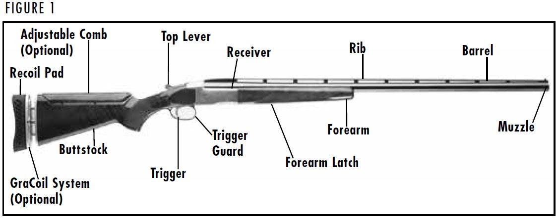
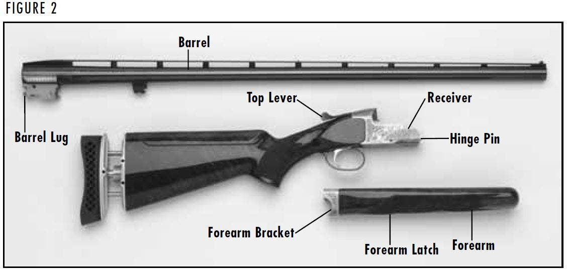
In conventional firearm terminology the position and movement of firearm parts are described as they occur with the firearm horizontal and in normal firing position: i.e., the muzzle is forward or in front; the buttstock is rearward or to the rear; the trigger is downward or underneath; the rib is upward or on top. For general parts nomenclature, refer to Figure 1. For specific parts names related to disassembly, refer to Figure 2.
SERIAL NUMBER
The serial number of your BT-99 is found under the top lever. Record this number in the space provided at the front of this owner’s manual for future reference.
Initial Cleaning
Initial Cleaning
Various exposed metal parts of your new firearm have been coated at the factory with a rust preventative compound. Before assembling your shotgun, clean the anti-rust compound from the inside of the barrel, receiver and the action/chamber areas. A high-quality lightweight gun oil is ideal for removing this compound, and for giving your new firearm its first lubrication. Grease is recommended to lubricate the hinge pin, barrel lugs and forearm bracket to prevent possible galling. Clean the barrel using a cleaning rod and patch as explained under the “Cleaning and Maintenance Suggestions” section.

NOTICE: THE BROAD, POLISHED, FINELY FITTED SURFACES OF THE RECEIVER AND FOREARM MECHANISMS (BARREL LUGS, HINGE PIN AND FOREARM BRACKET) MUST ALWAYS BE COATED WITH A FILM OF HIGH QUALITY GREASE.
WARNING: THE BT-99 DOES NOT HAVE A “SAFETY” MECHANISM. UNLESS SHOOTING IS IMMINENT KEEP THE ACTION OPEN AND THE CHAMBER UNLOADED. DO NOT LOAD THE CHAMBER UNLESS SHOOTING IS IMMINENT. ALWAYS KEEP THE MUZZLE POINTED IN A SAFE DIRECTION. FAILURE TO FOLLOW THESE WARNINGS COULD RESULT IN SERIOUS INJURY OR DEATH.
No "Safety" Mechanism
No "Safety" Mechanism
The BT-99 is designed solely for trap shooting. A trap shooter does not load his or her gun until moments before calling for a target. For this reason, and because trapshooting demands intense concentration on shooting technique, no “safety” mechanism is provided. Then, there is then no chance for a lost target by reason of the “safety” being inadvertently left in the on safe position. Remember:
- When leaving or moving along the line always open the action and unload the chamber.
- Never have the action of your BT-99 closed except when you are on the line and ready to shoot, your gun is cased, or it is set in a gun rack at the range.
- Never load the chamber until you are ready to shoot. Load your shotgun only when shooting is imminent.
- Always keep the muzzle of your shotgun pointed down range when on the shooting line.
- When you retrieve your shotgun from its case or from a gun rack, always immediately open the action and check to assure that no shell is in the chamber.
Top Lever
Top Lever
The top lever operates the locking bolt, which is hand fitted to the barrel lugs. Moving the top lever to the right unlocks the action and allows the shotgun to be loaded and unloaded.
It is not necessary that the top lever return to a completely centered position, nor should it be hanging over the right side or edge of the receiver tang as you look down on it. Upon closing your gun, let the top lever snap into position to allow the top lever spring to return the top lever mechanism to the locked position. Do not retard its action with your thumb. Many shooters lightly push the top lever to the left after closing the breech. This operation is a quick method of assuring yourself that foreign matter has not interfered with the complete closure of the breech.
Always keep the polished breech surfaces clean and lightly lubricated. The breech is so carefully hand fitted that accumulated debris, sand, etc. may prevent complete closing. If this should occur the action will not close. Open the gun and unload it. Carefully examine the action surfaces and remove any foreign matter.
WARNING: ALWAYS KEEP THE MUZZLE POINTED IN A SAFE DIRECTION. BEFORE STARTING ASSEMBLY PROCEDURES, VISUALLY INSPECT THE CHAMBER TO BE ABSOLUTELY CERTAIN THE FIREARM IS COMPLETELY UNLOADED. FAILURE TO FOLLOW THIS WARNING COULD RESULT IN SERIOUS INJURY OR DEATH.
Assembly
Assembly
The BT-99 is delivered in the box with the barrel removed and the forearm attached to the barrel. It is important to follow the exact sequence for assembly in order to properly assemble your shotgun.
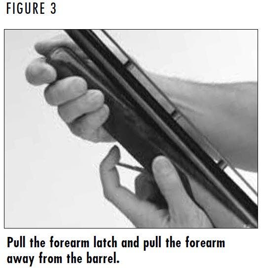
1. Remove the forearm from the barrel by pulling outward on the forearm latch and pivoting the front of the forearm down and away from the barrel (Figure 3).
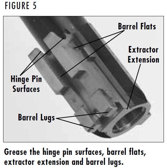
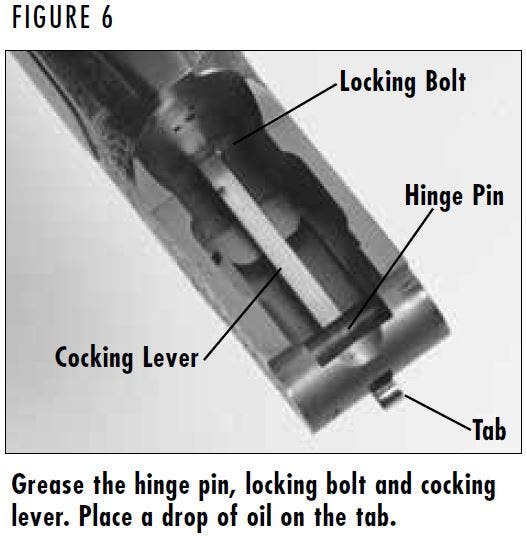
2. After cleaning exposed metal areas, apply a film of grease to the surfaces shown in Figure 4, Figure 5 and Figure 6. Apply a drop of oil to the tab.
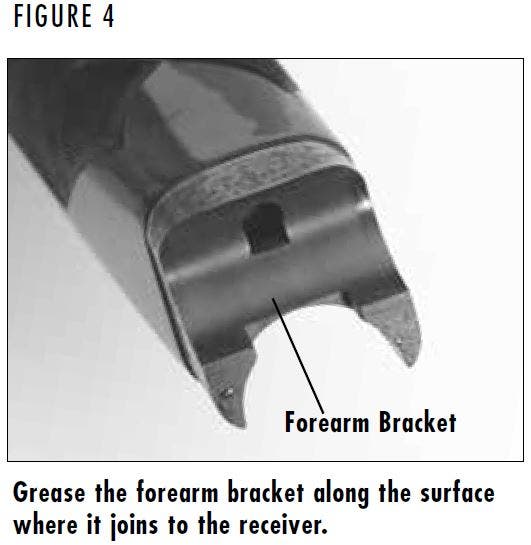
NOTICE: THE BROAD, POLISHED, FINELY FITTED SURFACES OF THE RECEIVER AND FOREARM MECHANISMS (BARREL LUGS, HINGE PIN AND FOREARM BRACKET) MUST ALWAYS BE COATED WITH A FILM OF HIGH QUALITY GREASE.
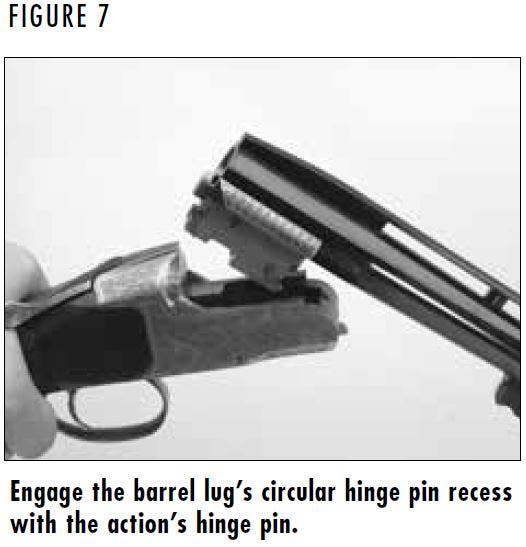
3. Attach the barrel to the action by grasping the buttstock’s grip with your right hand and anchoring the buttstock between your right forearm and right side. With the thumb of your right hand, move and hold the top lever sideways to the extreme right. Grasp the barrel in the left hand and engage the barrel lug’s circular hinge pin recess with the action’s hinge pin (Figure 7).
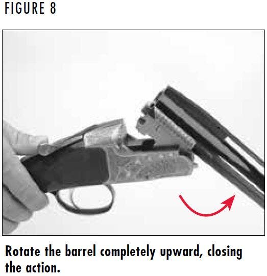
4. While keeping pressure on the barrel to keep the hinge pin aligned in the barrel lug’s circular recess, rotate the barrel upward, fully closing the action (Figure 8). Release the top lever. It should snap back into place.
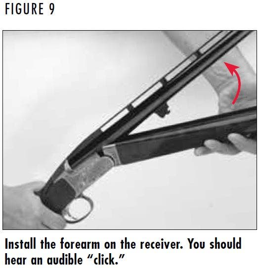
5. Slide the projecting steel tab on the rear of the forearm bracket into the opposing recess in the receiver bottom (Figure 9). Pivot the forearm up to the barrel tightly. This will cause the forearm to engage onto the barrel. You should hear an audible “click” which signifies that the forearm is properly attached.
NOTICE: WHEN ASSEMBLING YOUR SHOTGUN, DO NOT USE UNDUE FORCE WHEN CLOSING THE ACTION. IF THE TOP LEVER IS NOT TO THE RIGHT OR THE ACTION AND BARREL IS NOT PROPERLY ALIGNED UNDUE FORCE WILL ONLY CAUSE THEM TO GRIND TOGETHER AND SCORE OR MAR THE FINELY FITTED SURFACES. IF THERE APPEARS TO BE INTERFERENCE, START OVER AT STEP 3, BEING CAREFUL TO PROPERLY MATE AND ALIGN THE BARREL LUG’S HINGE PIN RECESS AND THE RECEIVER HINGE PIN.
WARNING: ALWAYS KEEP THE MUZZLE POINTED IN A SAFE DIRECTION. BEFORE STARTING DISASSEMBLY PROCEDURES, OPEN THE ACTION AND VISUALLY INSPECT THE CHAMBER TO BE ABSOLUTELY CERTAIN THE FIREARM IS COMPLETELY UNLOADED. FAILURE TO FOLLOW THIS WARNING COULD RESULT IN SERIOUS INJURY OR DEATH.
Disassembly
Disassembly
- Close the action, anchor the buttstock against your upper leg and lift outward on the forearm takedown latch. At the same time, grasp the forearm and with the help of the left hand pivot the forearm away from the barrel, removing the forearm.
- Open the action as explained previously. Carefully disengage the barrel lug from the hinge pin and lift the barrel upward and out of the action.
If you are disassembling for storage, reinstall the forearm on the barrel. You will then have two compact units: The barrel and forearm and the receiver and buttstock.
WARNING: DISCHARGING FIREARMS IN POORLY VENTILATED AREAS, CLEANING FIREARMS OR HANDLING AMMUNITION MAY RESULT IN EXPOSURE TO LEAD AND OTHER SUBSTANCES KNOWN TO CAUSE BIRTH DEFECTS, REPRODUCTIVE HARM AND OTHER SERIOUS PHYSICAL INJURY. HAVE ADEQUATE VENTILATION AT ALL TIMES. WASH HANDS THOROUGHLY AFTER EXPOSURE.
BT-99 SHOTGUNS ARE DESIGNED TO FIRE ONLY 12 GAUGE, 2¾" LOADS. USE ONLY SHELLS OF THE CORRECT GAUGE AND LENGTH. THE GAUGE AND LENGTH OF THE CHAMBER ARE INSCRIBED ON THE SIDE OF THE BARREL. DO NOT USE AMMUNITION OTHER THAN WHAT IS INSCRIBED ON THE SIDE OF THE BARREL. EXAMINE EVERY SHELL YOU PUT IN YOUR SHOTGUN. FAILURE TO FOLLOW THIS WARNING COULD RESULT IN SERIOUS INJURY OR DEATH AND CAUSE DAMAGE TO YOUR SHOTGUN.
USE SHELLS OF THE CORRECT LENGTH. DO NOT USE 3" OR 3½" SHELLS IN A BARREL WITH A 2¾" OR 2½" CHAMBER, OR 3½" SHELLS IN A BARREL WITH A 3" CHAMBER. DOING SO CAN RESULT IN A BUILDUP OF DANGEROUSLY HIGH PRESSURES. FAILURE TO FOLLOW THIS WARNING COULD RESULT IN SERIOUS INJURY OR DEATH AND CAUSE DAMAGE TO YOUR SHOTGUN.
DO NOT PUT A 16 OR 20 GAUGE SHELL IN A 12 GAUGE SHOTGUN. DO NOT PUT A 28 GAUGE SHELL IN A 20 GAUGE SHOTGUN. DO NOT PUT
A .410 BORE SHELL IN A 28 GAUGE SHOTGUN. NEVER PUT METALLIC CARTRIDGES OF ANY KIND IN A SHOTGUN. SPECIFICALLY, NEVER PUT CENTERFIRE RIFLE OR PISTOL CARTRIDGES IN A SHOTGUN CHAMBERED FOR .410 BORE. FAILURE TO FOLLOW THIS WARNING COULD RESULT IN SERIOUS INJURY OR DEATH AND CAUSE DAMAGE TO YOUR SHOTGUN.
Ammunition
Ammunition
The most certain way to bulge or rupture a shotgun barrel is to load a smaller gauge shell into a larger gauge chamber. The smaller gauge shell will not fall completely through the barrel; its rim is caught by the front of a larger gauge chamber or at the larger gauge’s choke. Your shotgun will misfire (with the chamber appearing to be empty). It is then possible to load the correct gauge shell behind the smaller gauge shell. If the shotgun is then fired, the result will be a so-called “12-16, 12-20, 20-28 or 28-.410 burst” which can cause extensive damage to your shotgun and possible serious injury to you and others.
The barrel and action of this firearm have been made with safety margins over the pressures established by the Sporting Arms and Ammunition Manufacturers’ Institute (SAAMI) for Service Cartridges. However, we assume no responsibility for incidents which occur through the use of cartridges of nonstandard dimension or those developing pressures in excess of SAAMI established standards.
BT-99 shotguns will shoot all factory lead and steel 12 gauge, 2¾" field and target loads.
WARNING: WHEN LOADING YOUR SHOTGUN ALWAYS KEEP THE MUZZLE POINTED IN A SAFE DIRECTION AND KEEP YOUR FINGERS AWAY FROM THE TRIGGER. FAILURE TO FOLLOW THESE WARNINGS COULD RESULT IN SERIOUS INJURY OR DEATH.
Loading
Loading
- Move the top lever to the right and open the breech.
- Check the chamber and bore to be certain they are clear of obstructions.
- Insert a shell completely into the chamber.
WARNING: NEVER LOAD A SHELL INTO THE CHAMBER UNLESS SHOOTING IS IMMINENT. ALWAYS KEEP THE MUZZLE POINTED IN A SAFE DIRECTION. FAILURE TO FOLLOW THESE WARNINGS COULD RESULT IN SERIOUS INJURY OR DEATH.
Firing
Firing
WARNING: THE SHOTGUN IS NOW READY TO FIRE BY SIMPLY PULLING THE TRIGGER.
BT-99 Plus models feature an ejector that ejects the empty hull from the chamber and lifts unfired shells. For proper ejection, keep the receiver level and allow the barrel to completely drop. This keeps empty hulls in full contact with the ejector.
It is important to point the breech, by canting the shotgun to the right (left for left-handed shooters), so empty hulls eject clear of your body and face. Fired hulls will be thrown completely out of the chamber upon opening the action; and unfired shells will be elevated above the chambers for unloading.
WARNING: AFTER FIRING, OR WHEN SHOOTING IS NO LONGER IMMINENT, IMMEDIATELY OPEN THE ACTION. KEEP THE MUZZLE POINTED IN A SAFE DIRECTION. FAILURE TO FOLLOW THESE WARNINGS COULD RESULT IN SERIOUS INJURY OR DEATH.
WARNING: WHILE UNLOADING YOUR SHOTGUN ALWAYS KEEP THE MUZZLE POINTED IN A SAFE DIRECTION, AND YOUR FINGERS AWAY FROM THE TRIGGER. FAILURE TO FOLLOW THESE WARNINGS COULD RESULT IN SERIOUS INJURY OR DEATH.
ALWAYS INSPECT THE CHAMBER AND BARREL CAREFULLY AFTER UNLOADING TO BE SURE ANY LIVE SHELL IS CLEARED FROM THE FIREARM.
Unloading
Unloading
1. Open the action by moving the top lever fully to the right. The action must be opened completely to reset the firing mechanism.
2. Due to close manufacturing tolerances, it may be necessary to pull downward slightly on the forearm to completely open the breech. BT-99 models have an automatic extractor that lifts a shell, fired or unfired, from the chamber of the shotgun when the action is opened. The shell can then be easily removed from the chamber with your fingers.
BT-99 Plus models feature an ejector that ejects the empty hull from the chamber and lifts unfired shells. For proper ejection, keep the receiver level and allow the barrel to completely drop. This keeps empty hulls in full contact with the ejector.
It is important to point the breech, by canting the shotgun to the right (left for left-handed shooters), so empty hulls eject clear of your body and face. Fired hulls will be thrown completely out of the chamber upon opening the action; and unfired shells will be elevated above the chambers for unloading.
IMPORTANT: Never have the action of your BT-99 closed except when you are on the line ready to shoot, when your firearm is cased, or when it is set in a gun rack at the range. Also, never load the chamber until you are ready to shoot. It is a courtesy to other shooters, and a wise safety practice, to keep the action open and unloaded at all other times.
WARNING: NEVER ATTEMPT TO REMOVE OR INSTALL A CHOKE TUBE IN A LOADED FIREARM. WHENEVER REMOVING OR INSTALLING A CHOKE TUBE IN YOUR BT-99 SHOTGUN ALWAYS KEEP THE MUZZLE POINTED IN A SAFE DIRECTION. OPEN THE ACTION AND MAKE ABSOLUTELY CERTAIN THE SHOTGUN IS COMPLETELY UNLOADED AND KEEP YOUR FINGERS AWAY FROM THE TRIGGER. FAILURE TO FOLLOW THESE WARNINGS COULD RESULT IN SERIOUS INJURY OR DEATH.

CAUTION: BROWNING INVECTOR-DS, INVECTOR-PLUS AND STANDARD INVECTOR CHOKE TUBES ARE NOT INTERCHANGEABLE. DO NOT USE BROWNING INVECTOR-PLUS, STANDARD INVECTOR OR INVECTOR-DS CHOKE TUBES IN ANY SHOTGUN BARREL NOT SUPPLIED BY BROWNING. DO NOT USE ANY OTHER CHOKING DEVICE IN ANY SHOTGUN BARREL SUPPLIED BY BROWNING.
USE ONLY THE APPROPRIATE GAUGE OF INVECTOR CHOKE TUBES IN THIS SHOTGUN. DO NOT FIRE THIS SHOTGUN WITHOUT THE CORRECT CHOKE TUBES INSTALLED. DAMAGE MAY RESULT TO THE THREADS INSIDE THE BARREL.
FAILURE TO FOLLOW THIS INFORMATION COULD RESULT IN DAMAGE TO YOUR SHOTGUN OR POSSIBLE INJURY.
NOTICE: USE ONLY THE INVECTOR CHOKE TUBE WRENCH SUPPLIED WITH YOUR SHOTGUN TO INSTALL AND REMOVE INVECTOR CHOKE TUBES. USING ANY OTHER WRENCH MAY DAMAGE THE THREADS IN THE BARREL.
Interchangeable Choke Tube System
Interchangeable Choke Tube System
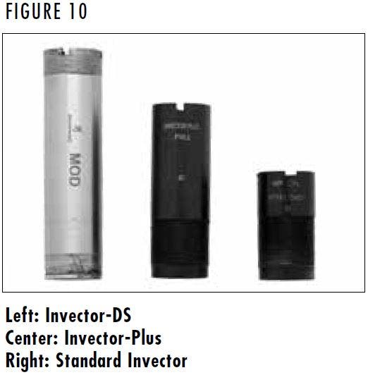
Current production BT-99 shotgun barrels are threaded to accept the Invector-Plus™ choke system. Browning Standard Invector, Invector-Plus and Invector-DS tubes are not interchangeable. Confirm the choke system of your shotgun by looking on the right side of the barrel where the specifications are inscribed, Invector choke tubes are identified in Figure 10 (flush mount tubes are shown).
The constriction of each choke tube is indicated twice on the choke tube: On the side of the tube, and indicated with a “notch” code on the top rim of the tube. The included choke tube T-Wrench is used to remove and install choke tubes.
Some target shotguns include premium extended choke tubes. The constriction of premium choke tubes is indicated twice on the choke tube: On the side of the tube, and indicated with an abbreviation in the colored band. The constriction of flush fit choke tubes is indicated twice on the choke tube: On the side of the tube, and indicated with a “notch” code on the top rim of the tube. The included choke tube wrench is used to remove and install extended choke tubes.
Invector choke tubes are compatible with factory ammunition that has been loaded in compliance with SAAMI specifications, including magnum lead and steel shot loads, sabots and slug loads.
Replacement and additional tubes and wrenches are available from your Browning dealer, or by contacting our Consumer Department. See the “Service or Repair” section for contact information.
CHOKE TUBE SELECTION
To help you choose the correct choke tube for each hunting and shooting situation, all Browning Invector choke tubes are inscribed on the side with the patterns they produce with both lead and steel shot. Each choke tube also has notches in the top rim of the tube (Figure 11). These notches are a code to allow you to determine the choke designation while the tube is installed. Rim notches refer specifically to lead shot. You will need to use the charts on the next page to cross-reference from lead to steel, and determine the appropriate tubes for your ammunition and hunting/shooting situation.
Most BT-99 shotguns include one choke tube. The choke tubes listed are available as accessories. Remember that Invector-DS, Invector-Plus and Standard Invector tubes are not interchangeable. Before removing or installing tubes, or reading the rim notch code, make sure your shotgun is completely unloaded.
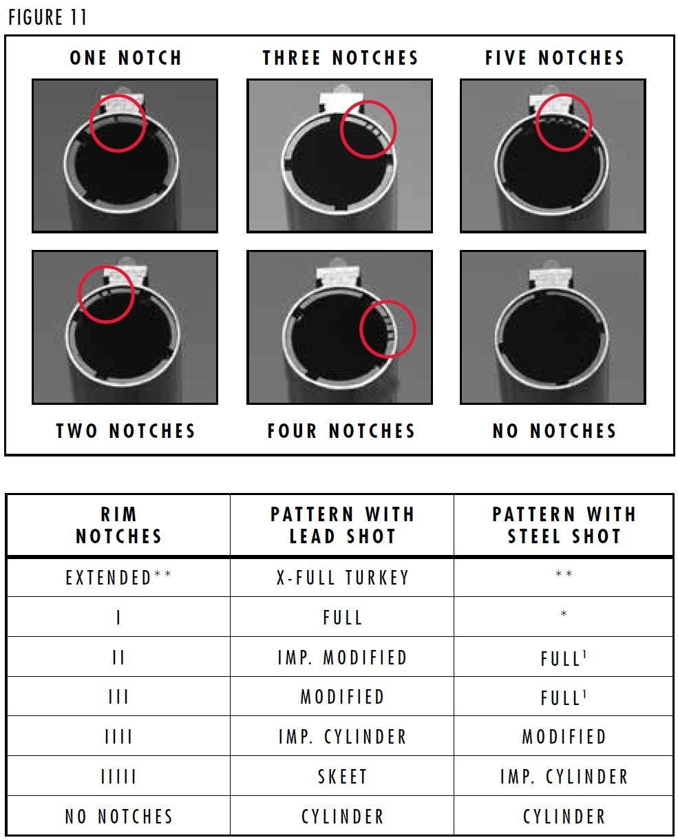
* Not for use with steel shot. Using an over-tight choke constriction with steel shot will result in an ineffective “blown” pattern.
** Extra Full Special, extended with ports. Do not use with steel shot.
1 When more than one choke designation is listed for a given steel shot pattern, use the more open choke listed for high velocity, larger shot size steel loads.
CHOKE TUBE REMOVAL
1. Make sure the shotgun is completely unloaded. Always keep the muzzle pointed in a safe direction.
2. Use the choke tube wrench to loosen the tube, turning it counterclockwise. Finger-twist the tube the rest of the way out of the barrel.
CHOKE TUBE INSTALLATION
1. Make sure the shotgun is completely unloaded. Always keep the muzzle pointed in a safe direction.
2. Before installing a tube, check the internal choke tube threads in the muzzle, as well as the threads on the choke tube to be sure they are clean. Lightly oil the threads with a high-quality, lightweight gun oil.
NOTICE: FAILURE TO CLEAN AND OIL THE THREADS ON THE CHOKE TUBE COULD RESULT IN THE CHOKE TUBE SEIZING IN THE BARREL.
3. Using your fingers, screw the appropriate tube into the muzzle of the barrel, tapered end first, notched end outward. When it becomes finger-tight, use the choke tube wrench to firmly seat the tube.
NOTICE: THE CHOKE TUBE SHOULD BE PERIODICALLY CHECKED TO ASSURE THAT IT IS TIGHT AND FIRMLY SEATED. BEFORE CHECKING, FOLLOW ALL CHOKE TUBE REMOVAL AND INSTALLATION SAFETY GUIDELINES PREVIOUSLY OUTLINED.
WARNING: BEFORE PERFORMING COMB ADJUSTMENT PROCEDURES OPEN THE ACTION AND MAKE CERTAIN YOUR SHOTGUN IS COMPLETELY UNLOADED. KEEP THE MUZZLE POINTED IN A SAFE DIRECTION. FAILURE TO FOLLOW THESE WARNINGS COULD RESULT IN SERIOUS INJURY OR DEATH.
Adjustable Comb Systems
Adjustable Comb Systems
The buttstock of some BT-99 shotguns features a comb that can be adjusted for both cast and drop. These adjustments allow you to achieve a perfect fit of the stock against your face, and determines how correctly and consistently your dominant eye aligns with the sight plane along the barrel rib. Different adjustable comb systems have been offered. Use this section to identify the style of comb on your shotgun and follow the instructions in that subsection to make adjustments.
ADJUSTABLE COMB TERMINOLOGY
With the gun shouldered, cast off means moving the comb to the right of the centerline of the gun to give a fit advantage for a right-handed shooter. Cast on refers to moving the comb to the left of the centerline, giving a fit advantage for a left-handed shooter. A shotgun that is correctly adjusted for cast will have you looking directly down the center of the rib with both the front and middle beads in exact alignment.
Adjusting the drop at the comb allows you to align your eye perfectly with the plane of the rib. The drop measurement is determined by measuring the distance between the plane formed by the top of the rib and the top of the comb itself. The higher the comb, the less drop there will be.
A correct sight picture for trap shooters should have you looking down the rib with the bottom of the front bead resting on the top of the middle bead. This forms a “figure eight” or “stacked” configuration. Some of the rib will be showing as you sight down, but no rib will show between the beads. Lining up the beads correctly each time you shoot is what’s important.
Cast and drop adjustments are a matter of trial and error. Adjust a little at a time until you obtain the desired sight picture on the rib. Right-handed shooters may desire some cast off, with left-handed shooters preferring some cast on. The terminology is the same for right- or left-handed shooters. The net effect is to move the comb to allow the face to move farther over the stock for better eye-to-rib alignment. When properly set, the front and rear sight beads should line up perfectly each time you shoulder your shotgun.
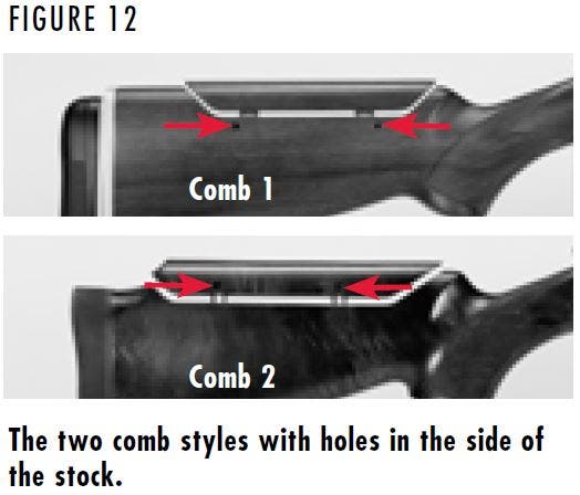
MODELS WITH ADJUSTMENT HOLES IN THE BUTTSTOCK OR COMB
This section explains how to adjust the cast and comb height on models with holes in the right side of the buttstock or comb (Figure 12). BT-99 models with these combs may or may not be equipped with the GraCoil® Recoil Reduction System. Both feature an approximate range of 1/4" of cast on or cast off adjustment and 5/8" of drop at comb adjustment.
CAST ADJUSTMENT
1. Open the action and make sure the shotgun is completely unloaded.
2. Remove the comb by inserting a 7/64" Allen wrench into the holes found on the right side of the buttstock. (Use a 3mm Allen wrench if the holes are in the comb.) Turn the wrench counterclockwise to loosen the Allen screws.
3. With the Allen screws loose, lift the comb from the stock.
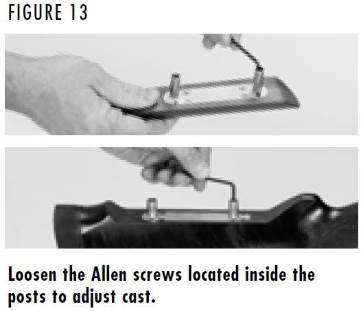
4. To adjust cast, loosen the two Allen screws located inside of the posts on the underside of the comb using a 7/64" Allen wrench (Figure 13). (If the posts are attached to the buttstock, use a 3mm Allen wrench to loosen the Allen screws inside the posts.)
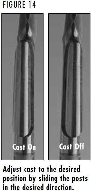
5. Adjust cast by sliding each post equally in the desired direction (Figure 14). Hash marks are stamped in the posts to aid in locating the posts on the comb. Each adjustment increment represents approximately 1/16".
- Move the posts to the right for more cast off.
- Move the posts to the left for more cast on.
6. With the posts adjusted, carefully secure the Allen screws inside the two posts. If drop at comb has already been set to your desired height, return the comb to your shotgun and carefully secure it to the buttstock by tightening the two Allen screws in the side of the buttstock or comb. Do not overtighten the screws. If drop has not been set, proceed to “Drop at Comb Adjustment.”
IMPORTANT: The posts must be inserted into the comb or buttstock a minimum of 3/8".
DROP AT COMB ADJUSTMENT
1. Open the action and make sure the shotgun is completely unloaded.
2. Remove the comb by inserting a 7/64" Allen wrench into the holes found on the right side of the buttstock. (Use a 3mm Allen wrench if the holes are in the comb.) Turn the wrench counterclockwise to loosen the Allen screws.
3. With the Allen screws loose, lift the comb from the stock.
4. If the comb of your shotgun is removed through holes in the buttstock, your shotgun included shims (20 were provided) to obtain the correct comb height. Add or remove an equal number of shims to each post to adjust drop at comb. A maximum of 10 (5/8" total height) of shims can be stacked per post.
If the comb of your shotgun is removed through holes in the comb or recoil pad, no shims were provided. With the Allen screws in the comb loose, carefully adjust drop at comb to desired height by sliding each post equally in the desired direction.
5. Once the comb height is adjusted, return the comb to your shotgun and carefully secure it to the buttstock by tightening the two Allen screws in the side of the buttstock or comb. Do not overtighten the screws. If cast has not been set, do not install the comb. Leave the Allen screws loose and read the directions under “Cast Adjustment.”
IMPORTANT: The posts must be inserted in the buttstock or comb a minimum of 3/8".
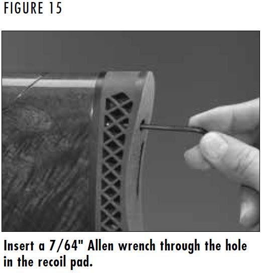
MODELS WITH A HOLE IN THE RECOIL PAD
This section explains how to adjust the cast and comb height on models with a single hole in the upper left side of the recoil pad (Figure 15). BT-99 models with this comb may or may not be equipped with the GraCoil® Recoil Reduction System. This comb features a total adjustment range of 1/4" of cast on and cast off adjustment and approximately 5/8" of total height adjustment. Adjustment increments are approximately 1/16".
CAST ADJUSTMENT (WITH GRACOIL® SYSTEM)
1. Open the action and make sure the shotgun is completely unloaded.
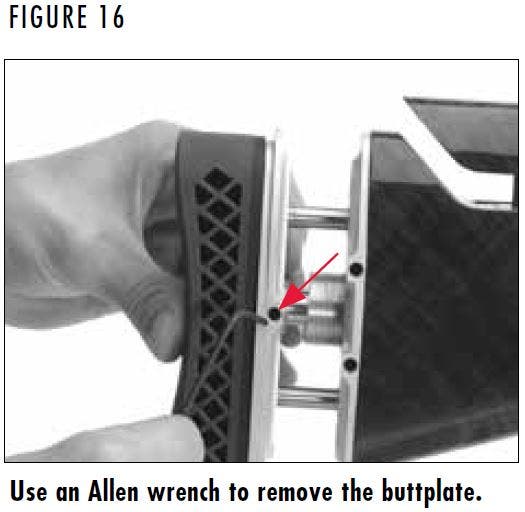
2. Remove the buttplate by inserting a 3/32" Allen wrench into the single hole on the right side of the buttplate and turn the set screw counterclockwise two turns to loosen the screw (Figure 16).
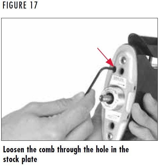
3. Loosen the comb by inserting a 7/64" Allen wrench through the hole found on the upper left of the stock plate and into the Allen screw located within the stock plate (Figure 17). Turn the wrench counterclockwise three full turns to loosen the Allen screw, allowing adjustments to be easily made.
4. With the Allen screw loose, carefully adjust comb to desired position (Figure 14) by sliding each post equally in the desired direction. Each adjustment increment represents approximately 1/16".
- Move the comb to the right for more cast off.
- Move the comb to the left for more cast on.
5. If drop at comb has already been set to your desired height, tighten the Allen screw in the stock plate and reinstall the recoil pad and buttplate. The screw needs to be firmly tightened, but be careful not to overtighten. If drop has not been set, leave the Allen screw loose and proceed to “Adjusting Drop at Comb.”
ADJUSTING DROP AT COMB (WITH GRACOIL® SYSTEM)
1. Open the action and make sure the shotgun is completely unloaded.
2. Remove the buttplate by inserting a 3/32" Allen wrench into the single hole on the right side of the buttplate and turn the set screw counterclockwise two turns to loosen the screw (Figure 16). Removing the buttplate gives access to the hole found on the upper left of the stock plate.
3. Loosen the comb by inserting a 7/64" Allen wrench through the hole found on the upper left of the stock plate and into the Allen screw located within the stock plate (Figure 17). Turn the wrench counterclockwise three full turns to loosen the Allen screw and allow adjustments to be easily made.
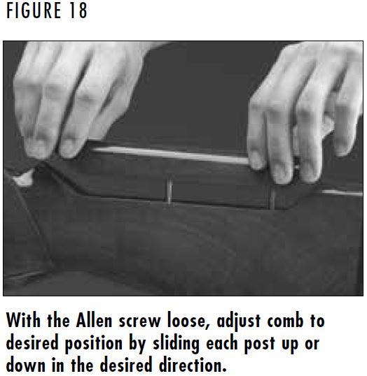
4. With the Allen screw loose, carefully adjust the comb to desired position (Figure 18) by raising or lowering each post equally in the desired direction. Sliding the posts equally will reduce the chance of the posts binding. Each increment represents 1/16" of movement.
- To decrease drop at comb, carefully slide the comb up.
- To increase drop at comb, carefully slide the comb down.
5. Once your desired drop at comb is obtained, tighten the Allen screw in the stock plate and reinstall the recoil pad and buttplate. The screw needs to be firmly tightened, but be careful not to overtighten.
ADJUSTING CAST ON AND CAST OFF (WITHOUT GRACOIL® SYSTEM)
The adjustable comb features a total adjustment range of 1/4" for cast on and cast off adjustment. Adjustment increments are approximately 1/16".
1. Open the action and make sure the shotgun is completely unloaded.
2. Insert the provided 7/64" Allen wrench through the hole found on the upper left of the recoil pad and into the Allen screw located within the recoil pad (Figure 15). Once the Allen wrench is engaged with the Allen screw, turn the wrench counterclockwise three full turns to loosen the Allen screw.
3. With the Allen screw loose, carefully adjust comb to desired position by sliding each post equally in the desired direction (Figure 14). Each adjustment increment represents approximately 1/16".
- Move the comb to the right for more cast off.
- Move the comb to the left for more cast on.
4. If drop at comb has already been set to your desired height, tighten the Allen screw in the recoil pad. The screw needs to be firmly tightened, but be careful not to overtighten. If drop has not been set, leave the Allen screw loose and proceed to “Adjusting Drop at Comb.”.
ADJUSTING DROP AT COMB (WITHOUT GRACOIL® SYSTEM)
The adjustable comb features a height adjustment range of 11 increments, 1/16" per increment, resulting in approximately 5/8" of total height adjustment.
NOTICE: DO NOT GO BEYOND THE RANGE OF ADJUSTMENT INCREMENTS. SHOULD THIS OCCUR, THE COMB WILL NOT BE PROPERLY SECURED TO THE SHOTGUN AND COULD RESULT IN INJURY OR DAMAGE TO THE FIREARM.
1. Open the action and make sure the shotgun is completely unloaded.
2. Insert the provided 7/64" Allen wrench through the hole found on the upper left of the recoil pad and into the Allen screw located within the recoil pad (Figure 15). Once the Allen wrench is engaged with the Allen screw, turn the wrench counterclockwise three full turns to loosen the Allen screw.
3. With the Allen screw loose, carefully adjust the comb to desired position (Figure 18) by raising or lowering each post equally in the desired direction. Sliding the posts equally will reduce the chance of the posts binding. Each increment represents 1/16" of movement.
- To decrease drop at comb, carefully slide the comb up.
- To increase drop at comb, carefully slide the comb down.
4. Once your desired drop at comb is obtained, tighten the Allen screw in the recoil pad. The screw needs to be firmly tightened, but be careful not to overtighten.
The adjustable comb features a height adjustment range of 11 increments, 1/16" per increment, resulting in approximately 5/8" of total height adjustment.
WARNING: BEFORE PERFORMING BUTTPLATE ADJUSTMENT PROCEDURES OPEN THE ACTION AND MAKE CERTAIN YOUR SHOTGUN IS COMPLETELY UNLOADED. KEEP THE MUZZLE POINTED IN A SAFE DIRECTION. FAILURE TO FOLLOW THESE WARNINGS COULD RESULT IN SERIOUS INJURY OR DEATH.
Adjusting The Buttplate
Adjusting The Buttplate
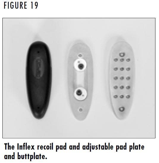
The buttplate on some BT-99 shotguns is adjustable to aid in dialing in the fit and sight picture of the shotgun (Figure 19). Adjustments to shotguns with and without the GraCoil® System are similar. To adjust the buttplate, perform the following:
1. Open the action and make sure the shotgun is completely unloaded.
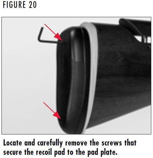
2. Remove the recoil pad by inserting a 3/32" Allen wrench into the two openings in the recoil pad and removing the two screws that secure the recoil pad (Figure 20). To prevent damage to the recoil pad, place a small amount of petroleum jelly on the Allen wrench. This will prevent the Allen wrench from grabbing and possibly tearing the recoil pad.
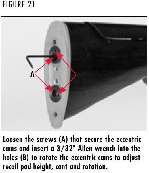
3. With a 3/32" Allen wrench, loosen the two set screws used to keep the eccentric cams in place (Figure 21).
4. Fifteen mounting holes on the buttplate let you position the recoil pad in the exact position to obtain the best possible gun fit.
Additionally, the two eccentric cams provide an even greater range of adjustments to optimize recoil pad height, cant and rotation. Adjust the eccentric cams until the desired position is achieved by inserting the 3/32" Allen wrench into the small hole adjacent to the Allen screw and turning the wrench to rotate the cam.
Pad plate adjustment is a matter of trial and error. Adjust in small increments until the desired pad plate position is reached.
5. Once the desired pad plate location is reached, tighten the two set screws that keep the cam locks in place with the 3/32" Allen wrench. Do not overtighten the set screws.
6. Reinstall the recoil pad by tightening the two screws with the 3/32" Allen wrench.
WARNING: BEFORE PERFORMING ADJUSTMENTS, OPEN THE ACTION AND MAKE CERTAIN YOUR SHOTGUN IS COMPLETELY UNLOADED. KEEP THE MUZZLE POINTED IN A SAFE DIRECTION. FAILURE TO FOLLOW THESE WARNINGS COULD RESULT IN SERIOUS INJURY OR DEATH.
Adjusting Length of Pull (Without GraCoil® System)
Adjusting Length of Pull (Without GraCoil® System)
Some BT-99 shotguns include a length of pull spacer that allows the stock to be shortened or lengthened to fit the shooter. To add or remove a spacer, perform the following:
- Open the action and make sure the shotgun is completely unloaded.
- Remove the recoil pad by inserting a 3/32" Allen wrench into the two openings in the recoil pad and removing the two screws that secure the recoil pad (Figure 20). To prevent damage to the recoil pad, place a small amount of petroleum jelly on the Allen wrench. This will prevent the Allen wrench from grabbing and possibly tearing the recoil pad.
- Add or remove spacers between the recoil pad and buttplate or recoil pad and buttstock to adjust length of pull.
- Once the desired length of pull is achieved, reinstall the recoil pad by tightening the two screws with the 3/32" Allen wrench. If using two spacers, use the longer screws provided to secure the recoil pad.
WARNING: BEFORE PERFORMING ADJUSTMENTS TO THE GRACOIL® SYSTEM, OPEN THE ACTION AND MAKE CERTAIN YOUR SHOTGUN IS COMPLETELY UNLOADED. KEEP THE MUZZLE POINTED IN A SAFE DIRECTION. FAILURE TO FOLLOW THESE WARNINGS COULD RESULT IN SERIOUS INJURY OR DEATH.
Adjusting The GraCoil® System
Adjusting The GraCoil® System
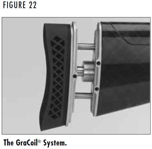
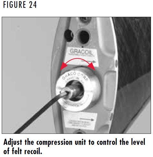
Some BT-99 shotguns include the GraCoil® Recoil Reduction System (Figure 22) that features an adjustable compression unit to reduce recoil, adjust length of pull and adjust the buttplate. The GraCoil® System is highly adjustable and allows you to tailor the firearm to suit your specific requirements.
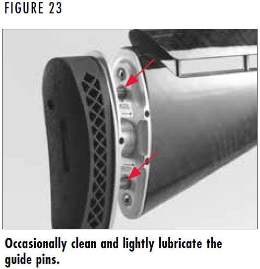
The guide pins on the buttplate slide on Teflon™ bushings (Figure 23,). This ensures long life and smooth action of the GraCoil® System. An occasional cleaning and light lubrication of the guide pins will help prevent premature wear. A light oil is suitable for lubrication.
ADJUSTING THE GRACOIL® RECOIL REDUCTION SYSTEM
When making adjustments to the GraCoil® Recoil Reduction System compression unit, be aware that the unit should be adjusted to the shooter, not to the shell size or loads being fired. When adjusted properly, the recoil from the shotgun will activate the GraCoil® System, effectively reducing the felt recoil experienced by the shooter.
The GraCoil® Recoil Reduction System features adjustable compression range from 14-70 lbs., with a 5/16" maximum stroke. To adjust the GraCoil® Recoil Reduction System, perform the following:
1. Open the action and make sure the shotgun is completely unloaded.
2. Loosen the buttplate by inserting a 3/32" Allen wrench into the single hole on the right side of the buttplate and turning the screw counterclockwise to loosen the screw (Figure 15).
3. Remove the buttplate by pulling it straight out. This exposes the center shaft where adjustments are made.
4. Insert the 3/32" Allen wrench into the hole in the center shaft and turn the wrench clockwise (light) to decrease the compression to the lightest setting (Figure 24). Do not force the compression adjustment screw.
5. To personalize the GraCoil® System, reinstall the recoil pad and bring the firearm to your shoulder as if you are ready to call for a target. If the unit compresses when you perform this action, the compression of the unit is set too light. Remove the pad again according to Step 2 and increase the compression one turn by inserting the 3/32" Allen wrench into the hole in the center shaft and turning the wrench counterclockwise (heavy) to increase compression.
Compression adjustments are a matter of trial and error. Adjust one turn at a time until the unit ceases to compress when brought to the shoulder. If the compression is too light, there will be excess motion from the gun when shouldering, thus affecting accuracy. If the compression is too heavy, more recoil will be felt.
WARNING: PROPER ADJUSTMENT OF THE GRACOIL® SYSTEM IS ESSENTIAL. FAILURE TO PROPERLY ADJUST THE COMPRESSION COULD RESULT IN PERSONAL INJURY. IF THE TENSION IS SET TOO LIGHT, THE UNIT COULD COMPRESS ENOUGH TO PINCH THE SHOOTER, RESULTING IN INJURY.
6. Once the gun can be shouldered without compressing the GraCoil® System, it is properly set-up and will effectively absorb recoil without affecting accuracy.
7. Reinstall the recoil pad and buttplate by sliding it back into the stock and tighten the set screws using the 3/32" Allen wrench. Do not overtighten the screws.
ADJUSTING LENGTH OF PULL
The GraCoil® System allows up to 1" of length of pull adjustment. To adjust the GraCoil® system for length of pull, perform the following:
1. Open the action and make sure the shotgun is completely unloaded.
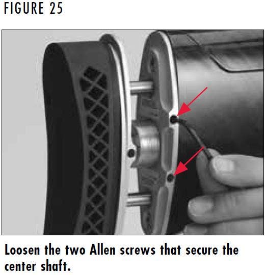
2. With a 7/64" Allen wrench, loosen the two set screws on the right side of the stock plate by turning them counterclockwise one turn (Figure 25).
3. Loosen the buttplate by inserting a 3/32" Allen wrench into the single hole on the right side of the buttplate and turning the screw counterclockwise to loosen the screw (Figure 14).
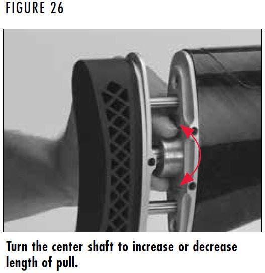
4. With your fingers, turn the large, threaded center shaft to adjust length of pull (Figure 26).
- Turn the shaft clockwise to decrease the length of pull.
- Turn the shaft counterclockwise to increase length of pull.
NOTICE: DO NOT USE A WRENCH OR PLIERS TO TURN THE CENTER SHAFT. DAMAGE TO THE SHAFT WILL OCCUR.
5. Length of pull adjustment is a matter of trial and error. Adjust in small increments until desired length of pull is reached.
6. When the desired length of pull has been achieved, tighten the two set screws on the stock plate using the 7/64" Allen wrench and single set screw on buttplate using the 3/32" Allen wrench. Do not overtighten the set screws.
7. It is possible that the settings on the recoil reduction unit of your shotgun may have changed after adjusting the length of pull. Before firing your shotgun, check to make sure your settings have not changed. If they have, refer to the last section and follow the directions to adjust the recoil reduction unit to your needs.
WARNING: BEFORE CHANGING TRIGGERS OR PERFORMING ADJUSTMENT PROCEDURES, OPEN THE ACTION AND MAKE CERTAIN THE CHAMBER IS UNLOADED. KEEP THE MUZZLE POINTED IN A SAFE DIRECTION. FAILURE TO FOLLOW THESE WARNINGS COULD RESULT IN SERIOUS INJURY OR DEATH.
Triple Trigger Systems
Triple Trigger Systems
The Triple Trigger System has three interchangeable trigger shoes with different surfaces: Wide with checkered surface, wide with canted smooth surface and narrow with smooth surface. Each trigger shoe is adjustable to three positions for length of pull.
REMOVING THE TRIGGER
- Open the action and make sure the shotgun is completely unloaded.
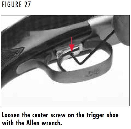
- Loosen the center screw with the provided 2mm Allen wrench (Figure 27) so the trigger shoe slides easily on the trigger plate. Keep the screw threaded at least one thread into the trigger shoe so the screw is not lost.
- Slide the trigger shoe forward to the end of the trigger plate. Press the rearward end of the trigger plate down with your finger and gently slide the trigger shoe off the trigger plate.
- Replace the trigger shoe by pressing the rearward end of the trigger plate and slide the trigger shoe down the side grooves of the plate.
CHANGING THE LENGTH OF PULL
- Open the action and make sure the shotgun is completely unloaded.
- Loosen the center screw with the provided 2mm Allen wrench (Figure 27) so the trigger shoe slides easily on the trigger plate. Keep the screw threaded at least one thread into the trigger shoe so the screw is not lost.
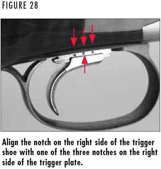
- Select the length of pull by lining up the notch on the right side of the trigger shoe with one of the three notches on the right side of the trigger plate (Figure 28). Make sure you line up the notches so you do not mar the trigger plate. When the notches are properly aligned the screw on the trigger shoe will seat in one of three recesses on the bottom of the trigger plate.
- Use a 2mm Allen wrench to tighten the screw on the trigger. Be certain the trigger shoe is secure before firing, and periodically check the shoe for any looseness as part of your cleaning and general maintenance procedures.
WARNING: BEFORE PERFORMING CLEANING PROCEDURES OPEN THE ACTION AND MAKE CERTAIN YOUR SHOTGUN IS COMPLETELY UNLOADED. KEEP THE MUZZLE POINTED IN A SAFE DIRECTION. FAILURE TO FOLLOW THESE WARNINGS COULD RESULT IN SERIOUS INJURY OR DEATH.
WARNING: WEAR EYE PROTECTION WHEN DISASSEMBLING AND CLEANING YOUR SHOTGUN TO PREVENT SOLVENTS OR OTHER AGENTS FROM CONTACTING YOUR EYES, RESULTING IN INJURY.
WARNING: KEEP ALL AMMUNITION AWAY FROM THE CLEANING AREA. NEVER TEST THE MECHANICAL FUNCTION OF YOUR SHOTGUN WITH LIVE AMMUNITION. FAILURE TO FOLLOW THESE WARNINGS COULD RESULT IN SERIOUS INJURY OR DEATH.
Cleaning and Maintenance Suggestions
Cleaning and Maintenance Suggestions
CLEANING PROCEDURES
Your BT-99 shotgun will function better and more reliably over a longer period of time if it is properly maintained and kept clean. The barrel should be cleaned and the action wiped clean and lubricated after every day of shooting, and more often if it becomes excessively dirty.
Normal maintenance can be accomplished with the barrel still attached to the receiver (lubricating and wiping down). More thorough cleaning requires removal of the barrel and forearm from the receiver (cleaning the barrel).
If you encounter a function problem (tight action when closing, etc.) or if a malfunction occurs, perform a thorough cleaning and lubrication to see if it solves the problem before seeking the services of a Browning Recommended Service Center, the Browning Service Facility in Arnold, Missouri, or a qualified gunsmith.
1. Open the action and make sure the shotgun is completely unloaded. Keep the muzzle pointed in a safe direction.
2. Remove the barrel and forearm from the receiver as explained under the “Disassembly” section.
3. Using a shotgun cleaning rod with tip and patch large enough for a snug fit in the bore, lightly oil the patch and insert the rod in the breech end of the barrel and run back and forth several times in the barrel.
Browning offers a complete line of products to make cleaning your firearm fast and easy. Be sure to follow all instructions when using any product to clean your firearm.
4. Inspect the bore from both ends for leading and plastic residue that often remains in the bore from the shot cups in modern shotshells. Leading and plastic residue will appear as longitudinal streaks and are usually more predominant near the muzzle and just forward of the chamber. A normal amount of either is common and is not serious.
5. If leading or plastic residue seems excessive you can remove it by brushing the bore with a brass brush. Soak the brush or spray the bore with a powder solvent first. Scrub until clean. To prevent bristles from breaking off, push the brush fully through each time before pulling it back through.
WARNING: MOST SOLVENTS ARE HIGHLY FLAMMABLE. WEAR EYE PROTECTION AND PRACTICE APPROPRIATE SAFETY MEASURES WHEN WORKING WITH SOLVENTS TO AVOID SERIOUS INJURY.
6. After all leading and plastic residues have been removed, run a clean, dry patch through the bore. Follow this with a final, lightly oiled patch.
7. Wipe all metal surfaces of the receiver, forearm and barrels with a clean rag. Then lubricate your gun at the points described in Step 2 under the “Assembly” section. Regular lubrication is extremely important to the durability and reliable operation of your shotgun.
NOTICE: THE BROAD, POLISHED, FINELY FITTED SURFACES OF THE RECEIVER AND FOREARM MECHANISMS (BARREL LUGS, HINGE PIN AND FOREARM BRACKET) MUST ALWAYS BE COATED WITH A FILM OF HIGH QUALITY GREASE.
NOTICE: DO NOT PLACE LARGE QUANTITIES OF OIL INTO THE ACTION. EXCESS OIL WILL RUN BACK INTO THE WOOD OF THE STOCK AND SOFTEN THE WOOD, WITH CONSEQUENTIAL LOOSENING OF THE STOCK.
8. Inspect the barrel and chamber to be certain no patches have inadvertently been left in them. Remove any that remain.
9. The wood surfaces can also be wiped with a quality, lightweight gun oil or they can be polished with any quality furniture wax (but not both).
10. It is very important that the chamber of your shotgun be cleaned thoroughly and promptly after shooting plastic shotshells. Do not leave a discharged (empty) shell in the chamber for any length of time. The chemical composition of many plastic shells contains moisture which can “sweat” out of the shell and onto the chamber surface, and possibly cause corrosion and rust.
NEVER ATTEMPT TO TAKE YOUR FIREARM APART FURTHER THAN EXPLAINED IN THIS OWNER’S MANUAL. YOUR FIREARM IS A SPECIALIZED, FINELY FITTED MECHANISM. YOU MAY PERMANENTLY DAMAGE IT BY ATTEMPTING TO DISASSEMBLE THE INNER MECHANISM ASSEMBLIES. IF FURTHER DISASSEMBLY FOR SERVICE OR CLEANING IS REQUIRED, TAKE YOUR FIREARM TO A QUALIFIED GUNSMITH, OR CONTACT OUR ARNOLD, MISSOURI SERVICE FACILITY AS EXPLAINED UNDER THE “SERVICE OR REPAIR” SECTION.
Barrel Porting
Barrel Porting
Some BT-99 models feature a ported barrel that reduces recoil and muzzle jump. Carbon can build up in the ports after shooting. To clean them use a good quality powder solvent and pipe cleaners to scrub away debris.
Maintenance of Oil Finish Stocks
Maintenance of Oil Finish Stocks
Keeping the oil-finished wood surfaces on your firearm looking their best requires only a small amount of maintenance. When the surfaces become spotted or dull, the affected area(s) can be treated using rubbing alcohol on a soft, lint free cloth and allowed to dry. A small amount of a linseed oil-based finish, such as Watco® Danish Oil Finish, Deft® Danish Oil Finish, or Formby’s® Tung Oil Finish should then be applied to the surface of the wood with a soft, lint free cloth according to the manufacturers’ instructions. To treat the checkering, a small amount of oil-based finish can be applied and then distributed evenly using a toothbrush or other soft bristled brush.
Models with Special Finishes
Models with Special Finishes
As with any gun, the only way to preserve its pristine condition and collector appeal is to never handle or fire it, which in turn would deprive you of much of the enjoyment that comes with owning a fine Browning firearm.
While special finishes such as engraving and gold plating greatly enhance the aesthetic appeal of your shotgun, please be aware that they are no more durable, and in some cases may even be slightly less durable than more common gun finishes.
As you use your Browning shotgun, you can expect special finishes to wear in much the same manner as any other firearm finish. These marks are the honest product of the hours spent enjoying your firearm and each scuff and scratch will probably have a good story to go along with it.
SERVICE OR REPAIR
SERVICE OR REPAIR
If your firearm should require service or repairs, we suggest you first contact a local recommended Browning Firearms Service Center. To locate a service center visit browning.com, contact our Customer Service Department or your Browning firearms dealer for the address of the Service Center nearest you. Otherwise, you may send your firearm directly to our Service Department in Arnold, Missouri.
Parts listings, Firearm Service Center lists, service procedures, service/repair form and general product information are also found on the internet at browning.com. For technical questions about your firearm or service, contact:
United States customers contact:
Browning Firearm Status and
Technical Service
3005 Arnold Tenbrook Rd
Arnold, MO 63010-9406
Phone: (800) 322-4626
Canadian customers contact:
Browning Canada Sports Ltd/Ltée
5583 Chemin St-François
St-Laurent, Quebec H4S 1W6
Phone: (514) 333-7261
When returning your firearm for servicing, you must do the following:
1. Be sure it is completely unloaded.
2. Remove any optics, optic mounts or other accessories.
3. Package it securely in a cardboard container.
4. Enclose the service/repair form available at browning.com or a letter that clearly describes the trouble experienced, the ammunition used and the repairs desired. Also include your name, e-mail address (if possible) and a daytime phone number where you can be reached.
5. Never return ammunition with your firearm. It is against postal and most commerce regulations.
BROWNING.COM
US: Morgan, Utah 84050-9326
CANADA: Browning Canada Sports Ltd/Ltée, St-Laurent, Quebec H4S 1W6
INTL: Parc Industriel des Hauts-Sarts, B-4040 Herstal, Belgium