

BT-99 Max High Grade Adjustable Rib Instructions Owner's Manual Supplement
BT-99 Max High Grade Adjustable Rib Instructions Owner's Manual Supplement

WARNING: ALWAYS KEEP THE MUZZLE POINTED IN A SAFE DIRECTION. BEFORE STARTING ADJUSTMENT OR DISASSEMBLY PROCEDURES, OPEN THE ACTION AND VISUALLY INSPECT THE CHAMBER TO BE ABSOLUTELY CERTAIN THE FIREARM IS COMPLETELY UNLOADED. FAILURE TO FOLLOW THIS WARNING COULD RESULT IN SERIOUS INJURY OR DEATH.
PLEASE READ AND UNDERSTAND ALL INSTRUCTIONS AND WARNINGS IN THE OWNER’S MANUAL SUPPLIED WITH YOUR SHOTGUN AND THOSE FOUND IN THIS SUPPLEMENT BEFORE USING YOUR NEW SHOTGUN. FAILURE TO FOLLOW THESE INSTRUCTIONS, OR FAILURE TO FOLLOW ANY SAFETY WARNING, MAY RESULT IN INJURY OR DEATH TO YOURSELF OR OTHERS, OR MAY CAUSE DAMAGE TO YOUR FIREARM.
If your shotgun owner’s manual is missing, contact the Browning customer service department immediately at (800) 333-3288 for a free copy, or download one online at browning.com.
WARNING: DISCHARGING FIREARMS IN POORLY VENTILATED AREAS, CLEANING FIREARMS OR HANDLING AMMUNITION MAY RESULT IN EXPOSURE TO LEAD AND OTHER SUBSTANCES KNOWN TO CAUSE BIRTH DEFECTS, REPRODUCTIVE HARM AND OTHER SERIOUS PHYSICAL INJURY. HAVE ADEQUATE VENTILATION AT ALL TIMES. WASH HANDS THOROUGHLY AFTER EXPOSURE.
WARNING: WEAR EYE PROTECTION WHEN DISASSEMBLING AND CLEANING YOUR SHOTGUN TO PREVENT SPRINGS, SPRING-LOADED PARTS, SOLVENTS OR OTHER AGENTS FROM CONTACTING YOUR EYES, RESULTING IN INJURY.
Description
Description
Browning BT-99 Max High Grade shotguns offer an adjustable rib that allows you to fine-tune the angle of the rib for point of impact (POI) and sight picture, resulting in improved shooting performance and higher scores.
WARNING: BEFORE ATTEMPTING TO ADJUST THE RIB ON YOUR SHOTGUN, OPEN THE ACTION AND MAKE CERTAIN YOUR SHOTGUN IS COMPLETELY UNLOADED. KEEP THE MUZZLE POINTED IN A SAFE DIRECTION. FAILURE TO FOLLOW THESE WARNINGS COULD RESULT IN SERIOUS INJURY OR DEATH.
Point of impact (POI) is determined by patterning a shot gun and determining the relationship between where you were aiming and where the actual center of the pattern is. The point of impact for the BT-99 Max High Grade and other shotguns with this style of adjustable rib is approximately 6"-8" above the point of aim at 40 yards. Point of impact above the actual aiming point allows you to keep the clay bird in view constantly — just above the rib — as you swing and shoot.
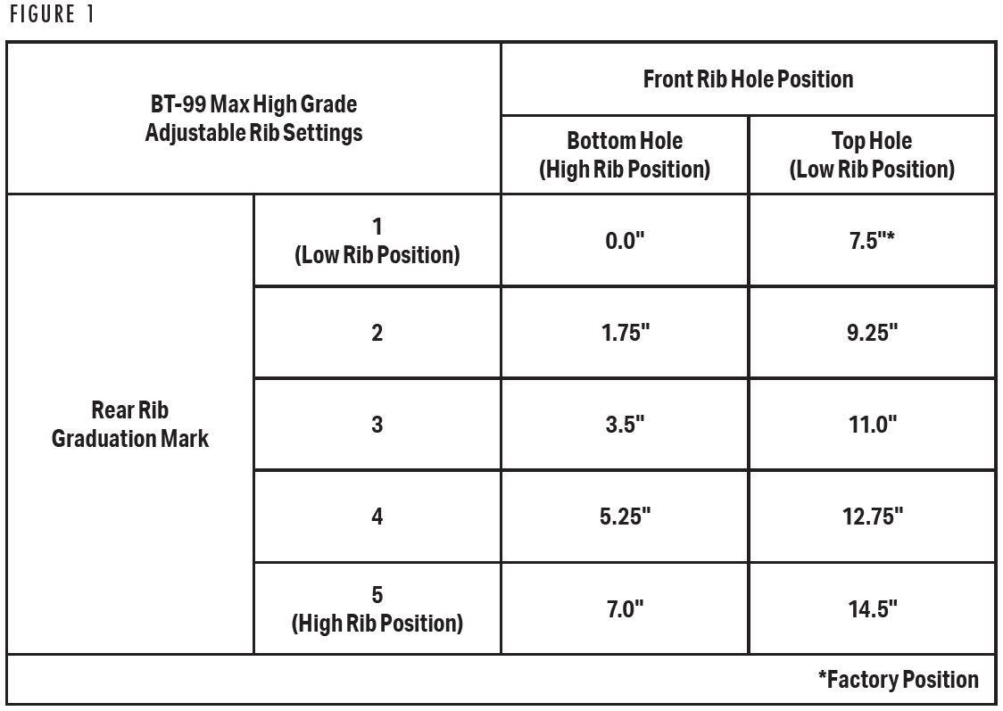
This style of adjustable rib has a point of impact adjustment range of approximately 0" to 14.5" above point of aim. Two approximate ranges of adjustment are available, 7.5" to 14.5" and 0" to 7". Changes are made, across the full range of adjustment, by a combination of moving the muzzle end of the rib to the higher or lower setting and adjusting the rib el evator screw at the receiver end of the rib. The information shown in the chart in Figure 1 will help determine which adjustments are necessary.
Adjusting Point of Impact
Adjusting Point of Impact
MAKING ADJUSTMENT S AT THE FRONT OF THE RIB
The rib at the muzzle end has two holes, one slightly higher than the other. Removing the pin and realigning the holes to the bottom or top position changes the rib height at the muzzle.
With the pin in the top hole position in the rib (low rib position) you have an approximate point of impact adjustment range from 7.5" to 14.5" above point of aim. With the pin in the bottom hole position in the rib (high rib position) you have an approximate point of impact adjustment range from 0" to 7" above point of aim. If you want to change the range to 0" to 7" above point of aim, or return it to the 7.5" to 14.5" setting, perform the following operation:
1. Secure your shotgun in a padded vice, if possible. If no vice is available lay the shotgun on a surface that will hold the shotgun securely without damaging the finish.
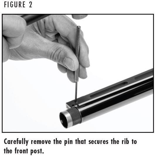
2. To help avoid damaging the finish on the shotgun, use the rib adjustment punch that was included with your shotgun or a 3/32" roll pin punch and a gunsmithing-type hammer to tap out the pin that secures the rib to the front post (Figure 2).

NOTICE: IT IS NOT NECESSARY TO REMOVE THE RIB TO ADJUST POI. TO REMOVE THE RIB TO PERFORM A THOROUGH CLEANING OF THE RIB ADJUSTMENT MECHANISMS, SEE “REMOVING AND REINSTALLING THE RIB” FOR INSTRUCTIONS.
3. With the pin removed, slide the front of the rib up or down to the desired position until the hole in the rib lines up with the slot in the post.
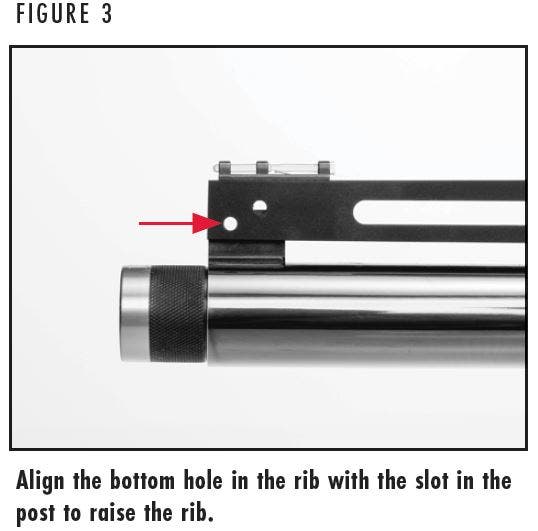
- To set the rib in the higher position, align the lower hole in the rib with the slot in the post as shown in Figure 3. The rib is pushed all the way up on the post in this position.
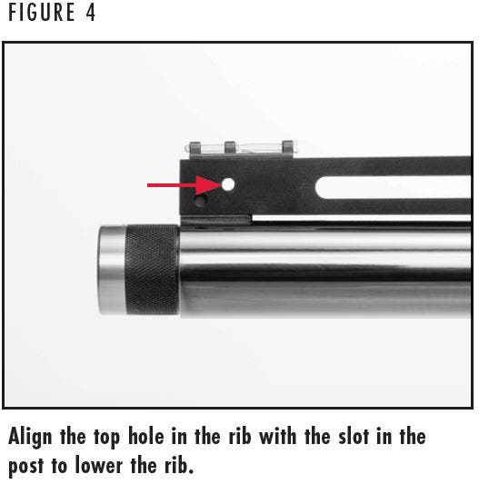
- To set the rib in the lower position, align the upper hole in the rib with the slot in the post as shown in Figure 4. The rib is pushed all the way down on the post in this position.
The amount of vertical change from one pin setting to the next seems small, but results in approximately a 7.5" change in point of impact at 40 yards.
4. To secure the rib in the desired setting, insert the roll pin into the desired hole and carefully tap the roll pin into position.
NOTICE: DO NOT FIRE THE SHOTGUN WITHOUT THE ROLL PIN IN PLACE.
MAKING ADJUSTMENTS AT THE REAR OF THE RIB
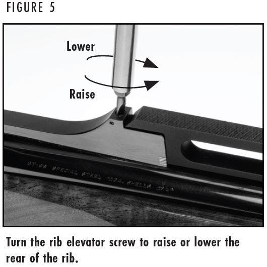
The rib is also adjustable at the rear of the rib by turning the rib elevator screw in or out with a blade-type screwdriver. As you turn the screw you will hear and feel a click. Each click represents approximately 3/8" of adjustment in point of impact at 40 yards. The graduation marks located near the back of the rib illustrate the height of the rear of the rib. When aligned with the bottom of the rib, each mark represents approximately 1.75" of point of impact change at 40 yards. Use the chart on page 3 to help set your desired height at the rear of the rib.
- Turning the rib elevator screw in (clockwise) lowers the point of impact.
- Turning the rib elevator screw out (counterclockwise) raises the point of impact.
1. To set a specific point of impact, first set the front rib position (if necessary) to the range of adjustment you require.
2. Insert a blade-type screwdriver into the rear elevation screw (Figure 5) and rotate it clockwise to the full down position (if it is not already in that position) to lower point of impact. Turning the rear adjustment screw in is easier if you press down lightly on the rib. Placing the rear elevator screw in the fully down position will put the point of impact 0" above (with the front of the rib in the higher position) or 7.5" above point of impact (with the front of the rib in the lower position).
3. Using the blade-type screwdriver, turn the screw out (counterclockwise) to raise point of impact. Placing the rear elevator screw in the fully up position will put the point of impact at 7" above (with the front of the rib in the higher position) or 14.5" above point of impact (with the front of the rib in the lower position).
NOTICE: TAKE CARE NOT TO FORCE THE SCREW BEYOND ITS MAXIMUM UP OR DOWN TRAVEL.
When your desired point of impact is achieved, the rib requires no further settings. The click mechanism will retain your point of impact setting.
4. Resetting your drop at comb measurements may also be necessary whenever the plane of the rib is changed to alter the point of impact.
Removing and Reinstalling the Rib
Removing and Reinstalling the Rib
Removing the rib from the barrel to adjust point of impact is unnecessary. However, the rib may be removed should cleaning be required. Carefully follow the instructions in this section to help prevent damaging the rib.
REMOVING THE RIB
1. Raise the rear of the rib by turning the rib elevator screw out (counterclockwise) until it is as high as it will go, as explained in step 3 under the “Making Adjustments at the Rear of the Rib” section.
NOTICE: DO NOT FORCE THE RIB ELEVATOR SCREW BEYOND ITS MAXIMUM UP OR DOWN TRAVEL.
2. Remove the roll pin at the front of the rib as explained in steps 1 and 2 under the “Making Adjustments at the Front of the Rib” section.
3. Lift up on the muzzle end of the rib approximately 30°. Carefully lift the rib forward and out from the rear rib elevator housing (Figure 6).
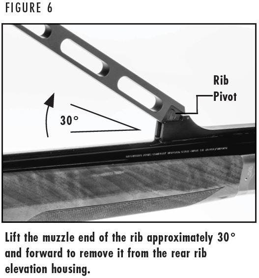
NOTICE: NEVER ATTEMPT TO REMOVE THE RIB BY LIFTING ON THE FRONT OF THE RIB WITHOUT THE REAR RIB ADJUSTMENT FULLY RAISED.
4. With the rib removed be careful not to lose the rib pivot. It is the circular part with a shoulder on each side that is fitted into the rib (Figure 6, page 7). It is easily removed and reinserted.
5. Removing the rib exposes the elevator detent spring which is inserted, large end first, into the groove in the rear rib elevator housing with the bend facing up. It is unnecessary to remove this spring.
6. Clean and lightly oil all rib components as necessary.
INSTALLING THE RIB
1. Make sure the elevator detent spring is installed as explained in step 5 under “Removing the Rib” and the elevation screw is turned fully counterclockwise.
2. Insert the rear of the rib into the rib elevator housing with the front of the rib up approximately 30°. Make sure that the shoulders on the rib pivot are aligned with the grooves in the rear rib elevator housing.
3. Lower the front of the rib down onto the front rib post and secure the front of the rib with the roll pin to your point of aim specifications as explained in step 4 under “Making Adjustments at the Front of the Rib.”