


MAXUS II SHOTGUN Owner's Manual
MAXUS II SHOTGUN Owner's Manual
Important operating instructions for: BROWNING MAXUS II® AUTOLOADING SHOTGUNS
If you have any questions about your new firearm, this owner’s manual or other Browning products, contact:
Browning Customer Service
One Browning Place
Morgan, UT 84050-9326
Phone: (800) 333-3288
browning.com
Please use the space below to record information about your new firearm.
Model __________________________________________________
Serial Number ____________________________________________
Purchased From __________________________________________
Date of Purchase __________________________________________
THANK YOU FOR CHOOSING BROWNING.
The Maxus II shotgun represents the most advanced gas-operated technology available in autoloading shotguns. Maxus II shotguns combine the best of traditional Browning craftsmanship with state-of-the-art design and manufacturing. Every detail of the
Maxus II shotgun is engineered to provide you the best in reliable operation and handling.
With a reasonable amount of care, your Maxus II shotgun is designed to give you many years of dependable, enjoyable service.
Specifications within this owner’s manual are correct at the time of printing and subject to change without notice.
Contents
WARNING: You are Responsible for Firearms Safety
General Description and Operation
Nomenclature
Serial Number
Initial Cleaning
Operation of the “Safety”
Assembly
Disassembly
Ammunition
Magazine Capacity
Three-Shot Adaptor (Plug)
Loading
Firing
Unloading
Interchangeable Choke Tube System
Adjusting Length of Pull
Adjusting Cast and Drop at Comb
Installing a Scope or Optics
Extra Barrels
Cleaning and Maintenance Suggestions
Servicing the Trigger Group
Servicing the Bolt Assembly
Lubricating the Action Tube and Spring
Maintenance of Oil Finish Stocks
Models with Special Finishes
Service or Repair
State-By-State Warnings

Warning: You Are Responsible For Firearms Safety. Failure to follow any of the following warnings could result in serious injury or death.
Warning: You Are Responsible For Firearms Safety. Failure to follow any of the following warnings could result in serious injury or death.
As a gun owner, you accept a set of demanding responsibilities. How seriously you take these responsibilities can be the difference between life and death.
There is no excuse for careless or abusive handling of any firearm. At all times handle this firearm and all other firearms with intense respect for their power and potential danger.
Please read and understand all of the cautions, warnings, notices, proper handling procedures and instructions outlined in this owner’s manual before using your new firearm.
1. ALWAYS KEEP THE MUZZLE OF YOUR FIREARM POINTED IN A SAFE DIRECTION EVEN THOUGH YOU ARE CERTAIN IT IS UNLOADED.
1. ALWAYS KEEP THE MUZZLE OF YOUR FIREARM POINTED IN A SAFE DIRECTION EVEN THOUGH YOU ARE CERTAIN IT IS UNLOADED.
Never point any firearm at anything you do not intend to shoot. Be extremely alert and aware of all persons and property within the range of your ammunition.
2. NEVER RELY TOTALLY ON YOUR FIREARM'S MECHANICAL “SAFETY” DEVICE. LIKE ANY MECHANICAL DEVICE, A “SAFETY” CAN SOMETIMES FAIL; IT CAN BE JARRED OR INADVERTENTLY MANIPULATED INTO AN UNSAFE CONDITION..
2. NEVER RELY TOTALLY ON YOUR FIREARM'S MECHANICAL “SAFETY” DEVICE. LIKE ANY MECHANICAL DEVICE, A “SAFETY” CAN SOMETIMES FAIL; IT CAN BE JARRED OR INADVERTENTLY MANIPULATED INTO AN UNSAFE CONDITION..
The word “safety” describes a firearm’s trigger block mechanism, sear block mechanism, hammer block mechanism or firing pin block mechanism. Mechanical “safeties” are designed to place your firearm in a safer status, and no guarantee can be made that the firearm will not fire even if the “safety” is in the on safe position. Mechanical “safeties” merely aid safe gun handling and are no excuse for pointing your firearm’s muzzle in an unsafe direction. See “Operation of the Safety” on for instructions on the operation of this firearm’s “safety.”
Remember, safe gun handling does not stop with your firearm’s mechanical “safety” devices, it starts there. Always treat this firearm with the respect due a loaded, ready-to-fire firearm.
Some firearms do not have a mechanical “safety.” Many target firearms, lever-action firearms and pistols do not have manual “safety” mechanisms. Therefore it is critical to read and understand the owner’s manual for every firearm which explains the safe operation of the firearm.
While it is a good idea to test your firearm’s mechanical “safety” periodically for proper function, never test the “safety” while your firearm is loaded or pointed in an unsafe direction.
3. WHENEVER YOU HANDLE ANY FIREARM, OR HAND IT TO SOMEONE, ALWAYS OPEN THE ACTION IMMEDIATELY AND VISUALLY CHECK THE FIREARM’S CHAMBER TO MAKE CERTAIN THAT THE FIREARM IS COMPLETELY UNLOADED.
3. WHENEVER YOU HANDLE ANY FIREARM, OR HAND IT TO SOMEONE, ALWAYS OPEN THE ACTION IMMEDIATELY AND VISUALLY CHECK THE FIREARM’S CHAMBER TO MAKE CERTAIN THAT THE FIREARM IS COMPLETELY UNLOADED.
Make certain the firearm does not inadvertently contain any ammunition. Remember, merely removing the magazine does not mean the chamber is unloaded. Always keep the chamber empty and the “safety” in the on safe position unless shooting is imminent.
4. ALWAYS WEAR EAR AND EYE PROTECTION WHEN SHOOTING.
4. ALWAYS WEAR EAR AND EYE PROTECTION WHEN SHOOTING.
Unprotected, repeated exposure to gunfire can cause hearing damage. Wear hearing protection (shooting earplugs or muffs) to guard against such damage.
Wear shooting glasses to protect your eyes from flying particles. Allow proper distance (eye relief) between a scope and your eye when firing a scoped rifle, shotgun or pistol. Do not use unorthodox shooting methods that could cause the rearward travel of the slide or bolt of a firearm to contact your eyes, face or hands. Always keep a safe distance between the muzzle of your firearm and any persons nearby, as muzzle blast, debris and ejecting shells could inflict serious injury.
Always wear eye protection when disassembling and cleaning any firearm to prevent the possibility of springs, spring-tensioned parts, solvents or other agents from contacting your eyes.
5. KEEP ALL FIREARMS UNLOADED DURING TRANSPORT, EVEN WHEN STORED IN A HOLSTER, GUN CASE, SCABBARD OR OTHER CONTAINER.
5. KEEP ALL FIREARMS UNLOADED DURING TRANSPORT, EVEN WHEN STORED IN A HOLSTER, GUN CASE, SCABBARD OR OTHER CONTAINER.
6. DROPPING OR JARRING A LOADED FIREARM CAN CAUSE ACCIDENTAL DISCHARGE.
6. DROPPING OR JARRING A LOADED FIREARM CAN CAUSE ACCIDENTAL DISCHARGE.
This can occur even with the “safety” in the on safe position. Be extremely careful while hunting or during any shooting activity to avoid dropping any firearm.
7. HUNTING FROM ELEVATED SURFACES SUCH AS TREESTANDS IS DANGEROUS.
7. HUNTING FROM ELEVATED SURFACES SUCH AS TREESTANDS IS DANGEROUS.
Doing so may increase the risk of mishandling a firearm. The following rules should always be observed by you and those you hunt with. Always make certain that the stand being used is safe and stable. Always make certain that your firearm is unloaded when it is being taken up and down from the stand. Always make certain that your firearm is not dropped from the stand, or dropped while it is being taken up or down from the stand. Remember, a loaded firearm may discharge when dropped, even with the “safety” in the on safe position.
8. STORE YOUR FIREARM AND AMMUNITION SEPARATELY, WELL BEYOND THE REACH OF CHILDREN.
8. STORE YOUR FIREARM AND AMMUNITION SEPARATELY, WELL BEYOND THE REACH OF CHILDREN.
Take prudent safeguards to ensure your firearm does not become available to untrained, inexperienced or unwelcome hands. Store all firearms in secure, locked cases or a gun safe. Keep your firearm unloaded when not in use.
9. BEWARE OF BARREL OBSTRUCTIONS.
9. BEWARE OF BARREL OBSTRUCTIONS.
Mud, snow and an infinite variety of other objects may inadvertently lodge in a barrel bore. It only takes a small obstruction to cause dangerously increased pressures that can damage your firearm and cause serious injury to yourself and others.
BEFORE CHECKING FOR A BARREL OBSTRUCTION, BE CERTAIN YOUR FIREARM IS COMPLETELY UNLOADED, THERE IS NOT A LIVE SHELL IN THE CHAMBER AND THE “SAFETY” IS IN THEON SAFE POSITION.
BEFORE CHECKING FOR A BARREL OBSTRUCTION, BE CERTAIN YOUR FIREARM IS COMPLETELY UNLOADED, THERE IS NOT A LIVE SHELL IN THE CHAMBER AND THE “SAFETY” IS IN THEON SAFE POSITION.
After assuring yourself that the firearm is completely unloaded, open the breech or action and look through the barrel to be sure it is clear of obstructions. If an obstruction is seen, no matter how small it may be, clean the bore with a cleaning rod and patch as described in this owner’s manual.
10. BE ALERT TO THE SIGNS OF AMMUNITION MALFUNCTION. IF YOU DETECT AN OFF SOUND OR LIGHT RECOIL WHEN A SHELL IS FIRED, DO NOT LOAD ANOTHER SHELL INTO THE CHAMBER.
10. BE ALERT TO THE SIGNS OF AMMUNITION MALFUNCTION. IF YOU DETECT AN OFF SOUND OR LIGHT RECOIL WHEN A SHELL IS FIRED, DO NOT LOAD ANOTHER SHELL INTO THE CHAMBER.
If your firearm fails to fire, keep the muzzle pointed in a safe direction for a minimum of 30 seconds. Rotate the ejection area of the firearm away from you, carefully open the action and remove the shell from the chamber. If the primer is indented, the defective shell should be disposed of in a way that cannot cause harm. If the primer is not indented, your firearm should be examined by a qualified gunsmith and the cause of the malfunction corrected before further use. Glance down the barrel to make sure that no obstructions remain in the barrel. Completely clear the barrel before loading and firing again. Failure to follow these instructions can cause extensive damage to your firearm and possible serious injury to yourself and others.
11. NEVER INSERT A SHELL OF THE INCORRECT GAUGE INTO ANY FIREARM.
11. NEVER INSERT A SHELL OF THE INCORRECT GAUGE INTO ANY FIREARM.
The gauge of your firearm is marked on the barrel. Store all shells of different gauges in completely separate and well-marked containers. Never store shells of mixed gauges in a common container or in your pockets.
12. EXAMINE EVERY SHELL YOU PUT IN YOUR FIREARM.
12. EXAMINE EVERY SHELL YOU PUT IN YOUR FIREARM.
We assume no responsibility for the use of unsafe or improper firearm and ammunition combinations or damage or injury caused by damaged ammunition. It is your responsibility to read and heed all warnings in this owner’s manual and on ammunition boxes
13. USE ONLY SAAMI APPROVED AMMUNITION.
13. USE ONLY SAAMI APPROVED AMMUNITION.
The barrel and action of this firearm have been made with substantial safety margins beyond the pressures developed by established American commercial loads. Nevertheless, we can assume no liability for incidents which occur through the use of shells of nonstandard dimensions or which develop pressures in excess of commercially available ammunition which has been loaded in accordance with standards established by the Sporting Arms and Ammunition Manufacturers’ Institute (SAAMI).
14. DISCHARGING FIREARMS IN POORLY VENTILATED AREAS, CLEANING FIREARMS OR HANDLING AMMUNITION MAY RESULT IN EXPOSURE TO LEAD AND OTHER SUBSTANCES KNOWN TO CAUSE BIRTH DEFECTS, REPRODUCTIVE HARM AND OTHER SERIOUS PHYSICAL INJURY. HAVE ADEQUATE VENTILATION AT ALL TIMES. WASH HANDS THOROUGHLY AFTER EXPOSURE.
14. DISCHARGING FIREARMS IN POORLY VENTILATED AREAS, CLEANING FIREARMS OR HANDLING AMMUNITION MAY RESULT IN EXPOSURE TO LEAD AND OTHER SUBSTANCES KNOWN TO CAUSE BIRTH DEFECTS, REPRODUCTIVE HARM AND OTHER SERIOUS PHYSICAL INJURY. HAVE ADEQUATE VENTILATION AT ALL TIMES. WASH HANDS THOROUGHLY AFTER EXPOSURE.
15. DO NOT SNAP THE FIRING PIN ON AN EMPTY CHAMBER; THE CHAMBER MAY NOT BE EMPTY!
15. DO NOT SNAP THE FIRING PIN ON AN EMPTY CHAMBER; THE CHAMBER MAY NOT BE EMPTY!
Treat every firearm with the respect due a loaded firearm, even though you are certain the firearm is unloaded.
16. KEEP YOUR FINGERS AWAY FROM THE TRIGGER WHILE LOADING AND UNLOADING UNTIL SHOOTING IS IMMINENT.
16. KEEP YOUR FINGERS AWAY FROM THE TRIGGER WHILE LOADING AND UNLOADING UNTIL SHOOTING IS IMMINENT.
17. BE SURE OF YOUR TARGET AND BACKSTOP, PARTICULARLY DURING LOW LIGHT PERIODS.
17. BE SURE OF YOUR TARGET AND BACKSTOP, PARTICULARLY DURING LOW LIGHT PERIODS.
Know the range of your ammunition. Never shoot at water or hard objects.
18. ALWAYS UNLOAD YOUR FIREARM’S CHAMBER BEFORE CROSSING A FENCE, CLIMBING A TREE, JUMPING A DITCH OR NEGOTIATING OTHER OBSTACLES.
18. ALWAYS UNLOAD YOUR FIREARM’S CHAMBER BEFORE CROSSING A FENCE, CLIMBING A TREE, JUMPING A DITCH OR NEGOTIATING OTHER OBSTACLES.
Never place your firearm on or against a fence, tree, car or other similar object.
19. BE DEFENSIVE AND ON GUARD AGAINST UNSAFE GUN HANDLING AROUND YOU AND OTHERS.
19. BE DEFENSIVE AND ON GUARD AGAINST UNSAFE GUN HANDLING AROUND YOU AND OTHERS.
Don’t be timid when it comes to firearms safety. If you observe other shooters violating any of these safety precautions, politely suggest safer handling practices.
20. BE CERTAIN YOUR FIREARM IS UNLOADED BEFORE CLEANING.
20. BE CERTAIN YOUR FIREARM IS UNLOADED BEFORE CLEANING.
Because so many firearm accidents occur when a firearm is being cleaned, special and extreme care should be taken to be sure your firearm is unloaded before disassembly, cleaning and reassembly. Keep ammunition away from the cleaning location. Never test the mechanical function of any firearm with live ammunition.
21. TEACH AND SUPERVISE FIREARMS SAFETY TO ALL MEMBERS OF YOUR FAMILY, ESPECIALLY TO CHILDREN AND NON-SHOOTERS.
21. TEACH AND SUPERVISE FIREARMS SAFETY TO ALL MEMBERS OF YOUR FAMILY, ESPECIALLY TO CHILDREN AND NON-SHOOTERS.
Closely supervise newcomers to the shooting sports. Encourage enrollment in hunting and shooting safety courses.
22. NEVER DRINK ALCOHOLIC BEVERAGES OR TAKE ANY TYPE OF DRUGS BEFORE OR DURING SHOOTING.
22. NEVER DRINK ALCOHOLIC BEVERAGES OR TAKE ANY TYPE OF DRUGS BEFORE OR DURING SHOOTING.
Your vision, motor skills and judgment could be dangerously impaired, making your gun handling unsafe to you and to others.
23. READ AND HEED ALL WARNINGS IN THIS OWNER’S MANUAL, ON AMMUNITION BOXES AND WITH ALL ACCESSORIES THAT YOU INSTALL ON YOUR FIREARM.
23. READ AND HEED ALL WARNINGS IN THIS OWNER’S MANUAL, ON AMMUNITION BOXES AND WITH ALL ACCESSORIES THAT YOU INSTALL ON YOUR FIREARM.
It is your responsibility to secure the most up-to-date information on the safe handling procedures of your Browning firearm. We assume no liability for incidents which occur when unsafe or improper firearm accessories or ammunition combinations are used.
24. PRACTICE PERIODIC MAINTENANCE, AVOID UNAUTHORIZED SERVICING.
24. PRACTICE PERIODIC MAINTENANCE, AVOID UNAUTHORIZED SERVICING.
Your firearm is a mechanical device which will not last forever, and as such, is subject to wear and requires periodic inspection, adjustment and service. Browning firearms should be serviced by a Browning Recommended Service Center or by our Service Facility in Arnold, Missouri. We assume no responsibility for injuries suffered or caused by unauthorized servicing, alterations or modifications of Browning firearms.
25. DO NOT, UNDER ANY CIRCUMSTANCES, ALTER THE TRIGGER, “SAFETY” OR OTHER PARTS OF THE FIRING MECHANISM OF THIS OR ANY OTHER FIREARM EXCEPT AS OTHERWISE DESCRIBED IN THIS MANUAL.
25. DO NOT, UNDER ANY CIRCUMSTANCES, ALTER THE TRIGGER, “SAFETY” OR OTHER PARTS OF THE FIRING MECHANISM OF THIS OR ANY OTHER FIREARM EXCEPT AS OTHERWISE DESCRIBED IN THIS MANUAL.
We reserve the right to refuse service on firearms that have been altered, added to or substantially changed. Removal of metal from the barrel, or modifications of the firing mechanism and/or operating parts may lead to a refusal of service on such firearms. You will be charged for parts and labor to return the firearm to original specifications prior to servicing your firearm.
With respect to AFTERMARKET PARTS OR COMPONENTS (including, for example, aftermarket trigger systems, barrels, muzzle brakes, suppressors, magazines, etc.), USE AT YOUR OWN RISK. Browning firearms are designed and engineered to meet stringent safety standards. Browning is not responsible for personal injuries or property damage caused by alterations to a firearm. This includes the incorporation of aftermarket parts or components that may or may not satisfy Sporting Arms and Ammunition Manufacturers’ Institute (SAAMI) standards (for example, an aftermarket trigger system may not satisfy SAAMI minimum trigger pull standards, etc.) or may create other dangerous conditions. These conditions may or may not be apparent to the user (for example, installing an aftermarket barrel may have the effect of altering critical firearm dimensions, including headspace, and may create an unsafe firing condition, etc.). Aftermarket parts or components that do not satisfy SAAMI standards, or that could create other dangerous conditions, should not be used.
FAILURE TO FOLLOW THIS WARNING COULD RESULT IN SERIOUS INJURY OR DEATH, AS WELL AS CAUSE DAMAGE TO YOUR FIREARM.
FAILURE TO FOLLOW THIS WARNING COULD RESULT IN SERIOUS INJURY OR DEATH, AS WELL AS CAUSE DAMAGE TO YOUR FIREARM.
BE CAREFUL!
BE CAREFUL!
General Description and Operation
The Browning Maxus II is a gas-operated, autoloading shotgun capable of quickly firing up to five shells (with the three-shot adaptor removed, using 2 ¾" loads), one shell at a time, with each successive pull of the trigger. Upon firing, high-pressure gases from behind the shot charge pass through two ports in the barrel, through the gas bracket and into the gas system, forcing it rearward. As the gas system moves rearward, it forces the bolt to the rear, operating the action. As the bolt moves rearward, it cocks the hammer and ejects the fired shell. After full rearward travel, the bolt returns forward, picks up a new shell from the magazine and chambers it. After the last shell has been fired, the bolt locks to the rear facilitating fast reloading.
Nomenclature
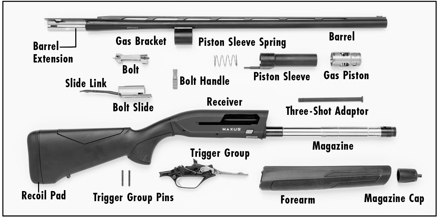
In conventional firearm terminology the position and movement of firearm parts are described as they occur with the firearm horizontal and in the normal firing position: i.e., the muzzle is forward or in front; the buttstock is rearward or to the rear; the trigger is downward or underneath; the rib is upward or on top. For general parts nomenclature, refer to Figure 1. For specific parts names related to disassembly, refer to Figure 2.
Serial Number
The serial number of your Maxus II shotgun is found on the right side of the receiver, below the bolt release button. Record this number in the space provided at the front of this owner's manual for future reference.
Figure 1
Figure 1
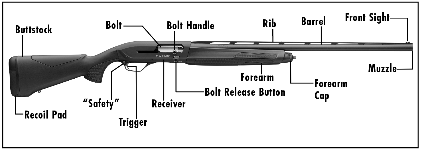
Figure 2
Figure 2
Initial Cleaning
Various exposed metal parts of your new firearm have been coated at the factory with a rust preventative compound. Before assembling your shotgun, clean the anti-rust compound from the inside of the barrel, receiver and the action/chamber areas. A high-quality lightweight gun oil is ideal for removing this compound, and for giving your new firearm its first lubrication. Place a drop of lightweight gun oil on both sides of the inside of the receiver on the rails on which the bolt slides (Figure 3, page 11). Clean the barrel using a cleaning rod and patch as explained under “Cleaning and Maintenance Suggestions”.
Figure 3
Figure 3
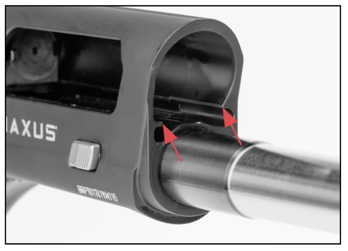
Lightly lubricate the bolt rails inside the receiver.
Operation of the “Safety”.
ALWAYS KEEP THE “SAFETY” IN THE ON SAFE POSITION UNLESS SHOOTING IS IMMINENT. ALWAYS KEEP THE MUZZLE POINTED IN A SAFE DIRECTION. FAILURE TO FOLLOW THESE WARNINGS COULD RESULT IN SERIOUS INJURY OR DEATH.
ALWAYS KEEP THE “SAFETY” IN THE ON SAFE POSITION UNLESS SHOOTING IS IMMINENT. ALWAYS KEEP THE MUZZLE POINTED IN A SAFE DIRECTION. FAILURE TO FOLLOW THESE WARNINGS COULD RESULT IN SERIOUS INJURY OR DEATH.
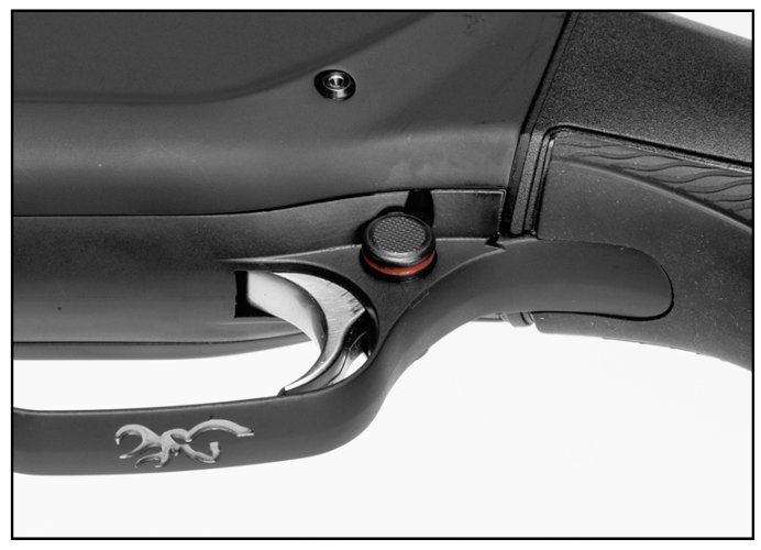
The “safety” is designed to prevent the trigger from being pulled when in the on safe position. The “safety” is located at the rear of the trigger guard (Figure 4). In the off safe position, a red warning band is visible on the safety button on the left side of the trigger guard.
To place the firearm on safe, press the “safety” button to the right.
To move the “safety” to the off safe or fire position, press the safety button to the left. This exposes the red warning band on the “safety” button (Figure 5).
To move the “safety” to the off safe or fire position, press the safety button to the left. This exposes the red warning band on the “safety” button (Figure 5).
Figure 4
Figure 4
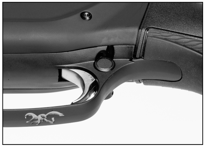
The “safety” shown in the on safe position.
Figure 5
Figure 5
The “safety” shown in the off safe position.
DO NOT DEPEND ON THE RED COLOR ALONE TO INDICATE YOUR FIREARM’S SAFETY STATUS. TIME, EXPOSURE TO THE ELEMENTS, AND THE ABRASIVE ACTION OF CLEANING AGENTS CAN ERASE IT. FAILURE TO FOLLOW THIS WARNING COULD RESULT IN SERIOUS INJURY OR DEATH.
DO NOT DEPEND ON THE RED COLOR ALONE TO INDICATE YOUR FIREARM’S SAFETY STATUS. TIME, EXPOSURE TO THE ELEMENTS, AND THE ABRASIVE ACTION OF CLEANING AGENTS CAN ERASE IT. FAILURE TO FOLLOW THIS WARNING COULD RESULT IN SERIOUS INJURY OR DEATH.
The “safety” can be reversed from right- to left-handed by a qualified gunsmith. When installed, the left-handed “safety” will have the “safety” button’s red warning band on the right side of the trigger guard. The “safety” is installed at the factory in the right-handed shooter position. Before using your shotgun, verify the installation of the “safety.” Instructions in this owner’s manual are for the “safety” installed in the right-handed position.
If you need to have the “safety” reversed on your shotgun, please contact an authorized Browning Firearms Service Center or send your shotgun to our Service Center in Arnold, Missouri. See page 51 for information on obtaining service for your Browning firearm.
ASSEMBLY
ALWAYS KEEP THE MUZZLE POINTED IN A SAFE DIRECTION. BEFORE STARTING ASSEMBLY PROCEDURES, VISUALLY INSPECT THE CHAMBER AND MAGAZINE TO BE ABSOLUTELY CERTAIN THE FIREARM IS COMPLETELY UNLOADED. PLACE THE “SAFETY” IN THE ON SAFE POSITION. FAILURE TO FOLLOW THIS WARNING COULD RESULT IN SERIOUS INJURY OR DEATH.
ALWAYS KEEP THE MUZZLE POINTED IN A SAFE DIRECTION. BEFORE STARTING ASSEMBLY PROCEDURES, VISUALLY INSPECT THE CHAMBER AND MAGAZINE TO BE ABSOLUTELY CERTAIN THE FIREARM IS COMPLETELY UNLOADED. PLACE THE “SAFETY” IN THE ON SAFE POSITION. FAILURE TO FOLLOW THIS WARNING COULD RESULT IN SERIOUS INJURY OR DEATH.
The Maxus II shotgun is delivered in the box with the barrel removed and the forearm attached to the magazine tube.
1. Lock the bolt rearward by pulling the bolt handle fully to the rear.

NEVER ALLOW THE ACTION TO SLAM CLOSED BY PRESSING THE BOLT RELEASE BUTTON WITHOUT THE BARREL INSTALLED. If the bolt is released forward with the barrel removed, the bolt handle will strike the receiver and cause damage
2. Remove the forearm from the magazine tube by unscrewing the magazine cap and sliding the forearm forward, off the magazine tube.
Figure 6
Figure 6
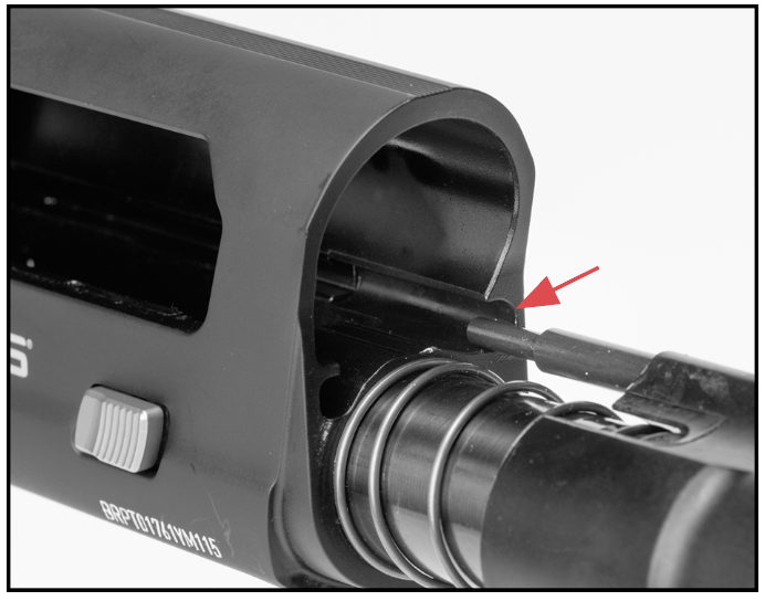
Align the push rod with the slot in the receiver.
Figure 7
Figure 7
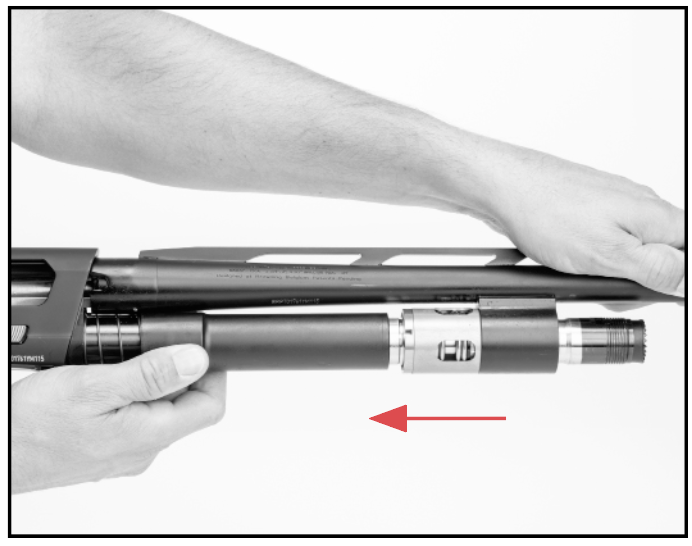
Slide the gas bracket and gas system components over the magazine tube and the barrel extension into the receiver.
Do not squeeze hard on the open rear end of a wood forearm. Too much pressure could cause the wood to split.
3. The gas system components (piston sleeve and gas piston) remain in place and do not need to be removed except for cleaning. If gas system components have been removed, reinstall them as explained below. Otherwise, proceed to step 5.
4. Slide the gas system components (piston sleeve and gas piston), push rod end first, onto the magazine tube. Align the push rod with the slot in the left side of the receiver (Figure 6). Make sure the gas system spring is properly positioned.
5. Align the barrel extension with the top of the receiver and place the gas bracket over the magazine tube (Figure 7). The barrel extension should slip solidly into the receiver. Make sure the push rod moves freely in its slot in the receiver.
6. Replace the forearm by sliding it onto the magazine tube and over the gas bracket so it seats securely.
7. Install the magazine cap, turning it clockwise until it is fully tightened down. Open and close the action several times and retighten the magazine cap.
DISASSEMBLY
ALWAYS KEEP THE MUZZLE POINTED IN A SAFE DIRECTION. BEFORE STARTING DISASSEMBLY PROCEDURES ,OPEN THE ACTION AND VISUALLY INSPECT THE CHAMBER AND MAGAZINE TO BE ABSOLUTELY CERTAIN THE FIREARM IS COMPLETELY UNLOADED. PLACE THE “SAFETY” IN THE ON SAFE POSITION. FAILURE TO FOLLOW THIS WARNING COULD RESULT IN SERIOUS INJURY OR DEATH.
ALWAYS KEEP THE MUZZLE POINTED IN A SAFE DIRECTION. BEFORE STARTING DISASSEMBLY PROCEDURES ,OPEN THE ACTION AND VISUALLY INSPECT THE CHAMBER AND MAGAZINE TO BE ABSOLUTELY CERTAIN THE FIREARM IS COMPLETELY UNLOADED. PLACE THE “SAFETY” IN THE ON SAFE POSITION. FAILURE TO FOLLOW THIS WARNING COULD RESULT IN SERIOUS INJURY OR DEATH.
1. Lock the bolt rearward by pulling the bolt handle fully to the rear.
2. Remove the forearm as explained previously.
DO NOT SQUEEZE HARD ON THE OPEN REAR END OF A WOOD FOREARM. TOO MUCH PRESSURE COULD CAUSE THE WOOD TO SPLIT.
3. For cleaning, remove the barrel and gas system components by sliding them forward and off the magazine tube. See “Cleaning and Maintenance Suggestions” for cleaning procedures.
For storage, remove the barrel and reinstall the forearm over the magazine tube. You will then have two compact units: The barrel, and the action with stock and forearm.
AFTER THE BARREL HAS BEEN REMOVED, LEAVE THE BOLT IN THE REARWARD POSITION. DO NOT PRESS THE BOLT RELEASE BUTTON. IF THE BOLT IS RELEASED FORWARD WITH THE BARREL REMOVED, THE BOLT HANDLE WILL STRIKE THE RECEIVER, CAUSING DAMAGE.
AMMUNITION
DISCHARGING FIREARMS IN POORLY VENTILATED AREAS, CLEANING FIREARMS OR HANDLING AMMUNITION MAY RESULT IN EXPOSURE TO LEAD AND OTHER SUBSTANCES KNOWN TO CAUSE BIRTH DEFECTS, REPRODUCTIVE HARM AND OTHER SERIOUS PHYSICAL INJURY. HAVE ADEQUATE VENTILATION AT ALL TIMES. WASH HANDS THOROUGHLY AFTER EXPOSURE.
DISCHARGING FIREARMS IN POORLY VENTILATED AREAS, CLEANING FIREARMS OR HANDLING AMMUNITION MAY RESULT IN EXPOSURE TO LEAD AND OTHER SUBSTANCES KNOWN TO CAUSE BIRTH DEFECTS, REPRODUCTIVE HARM AND OTHER SERIOUS PHYSICAL INJURY. HAVE ADEQUATE VENTILATION AT ALL TIMES. WASH HANDS THOROUGHLY AFTER EXPOSURE.
USE ONLY SHELLS OF THE CORRECT GAUGE AND LENGTH. THE GAUGE AND LENGTH OF THE CHAMBER IS INSCRIBED ON THE SIDE OF THE BARREL. DO NOT USE AMMUNITION OTHER THAN WHAT IS INSCRIBED ON THE SIDE OF THE BARREL. EXAMINE EVERY SHELL YOU PUT IN YOUR SHOTGUN. FAILURE TO FOLLOW THIS WARNING COULD RESULT IN SERIOUS INJURY OR DEATH.
USE ONLY SHELLS OF THE CORRECT GAUGE AND LENGTH. THE GAUGE AND LENGTH OF THE CHAMBER IS INSCRIBED ON THE SIDE OF THE BARREL. DO NOT USE AMMUNITION OTHER THAN WHAT IS INSCRIBED ON THE SIDE OF THE BARREL. EXAMINE EVERY SHELL YOU PUT IN YOUR SHOTGUN. FAILURE TO FOLLOW THIS WARNING COULD RESULT IN SERIOUS INJURY OR DEATH.
USE SHELLS OF THE CORRECT LENGTH. DO NOT USE 3" OR 3½" SHELLS IN A BARREL WITH A 2¾" CHAMBER, OR 3½" SHELLS IN A BARREL WITH A 3" CHAMBER. DOING SO CAN RESULT IN A BUILDUP OF DANGEROUSLY HIGH PRESSURES. FAILURE TO FOLLOW THIS WARNING COULD RESULT IN SERIOUS INJURY OR DEATH.
USE SHELLS OF THE CORRECT LENGTH. DO NOT USE 3" OR 3½" SHELLS IN A BARREL WITH A 2¾" CHAMBER, OR 3½" SHELLS IN A BARREL WITH A 3" CHAMBER. DOING SO CAN RESULT IN A BUILDUP OF DANGEROUSLY HIGH PRESSURES. FAILURE TO FOLLOW THIS WARNING COULD RESULT IN SERIOUS INJURY OR DEATH.
DO NOT PUT A 16 OR 20 GAUGE SHELL IN A 12 GAUGE SHOTGUN. DO NOT PUT A 28 GAUGE SHELL IN A 20 GAUGE SHOTGUN. DO NOT PUT A .410 BORE SHELL IN A 28 GAUGE SHOTGUN. NEVER PUT METALLIC CARTRIDGES OF ANY KIND IN A SHOTGUN. SPECIFICALLY, NEVER PUT CENTERFIRE RIFLE OR PISTOL CARTRIDGES IN A SHOTGUN CHAMBERED FOR .410 BORE. FAILURE TO FOLLOW THIS WARNING COULD RESULT IN SERIOUS INJURY OR DEATH.
DO NOT PUT A 16 OR 20 GAUGE SHELL IN A 12 GAUGE SHOTGUN. DO NOT PUT A 28 GAUGE SHELL IN A 20 GAUGE SHOTGUN. DO NOT PUT A .410 BORE SHELL IN A 28 GAUGE SHOTGUN. NEVER PUT METALLIC CARTRIDGES OF ANY KIND IN A SHOTGUN. SPECIFICALLY, NEVER PUT CENTERFIRE RIFLE OR PISTOL CARTRIDGES IN A SHOTGUN CHAMBERED FOR .410 BORE. FAILURE TO FOLLOW THIS WARNING COULD RESULT IN SERIOUS INJURY OR DEATH.
The most certain way to bulge or rupture a shotgun barrel is to load a smaller gauge shell into a larger gauge chamber. The smaller gauge shell will not fall completely through the barrel; its rim is caught by the front of a larger gauge chamber or at the larger gauge’s choke. Your shotgun will misfire (with the chamber appearing to be empty). It is then possible to load the correct gauge shell behind the smaller gauge shell. If the shotgun is then fired, the result will be a so-called “12-16, 12-20, 20-28 or 28-.410 burst” which can cause extensive damage to your shotgun and possible serious injury to you and others.
It is then possible to load the correct gauge shell behind the smaller gauge shell. If the shotgun is then fired, the result will be a so-called “12-16, 12-20, 20-28 or 28-.410 burst” which can cause extensive damage to your shotgun and possible serious injury to you and others.
The barrel and action of this firearm have been made with safety margins over the pressures established by the Sporting Arms and Ammunition Manufacturers’ Institute (SAAMI) for Service Cartridges. However, we assume no responsibility for incidents which occur through the use of cartridges of nonstandard dimension or those developing pressures in excess of SAAMI established standards.
Maxus II 12 gauge, 3" chamber models will shoot all 12 gauge, 2¾" and 3", 1 oz. and heavier factory lead and steel target loads. Maxus II 12 gauge, 3½" chamber models will shoot all 1 oz. and heavier factory lead and steel 12 gauge, 2¾", 3" and 3½" field loads.
MAGAZINE CAPACITY
With the magazine three-shot adaptor (plug) removed, A5 3" shotguns will hold four 2¾" or three 3" shells in the magazine. A5 3 1⁄2" shotguns will hold four 2 ¾" shells, or three 3" or 3 1⁄2" shells in the magazine.
THREE-SHOT ADAPTOR (PLUG)
ALWAYS KEEP THE MUZZLE POINTED IN A SAFE DIRECTION. BEFORE REMOVING OR INSTALLING THE THREE-SHOT ADAPTOR (PLUG), COMPLETELY UNLOAD THE SHOTGUN. OPEN THE ACTION AND VISUALLY INSPECT THE CHAMBER, FEED MECHANISM AND MAGAZINE TO BE ABSOLUTELY CERTAIN THE FIREARM IS COMPLETELY UNLOADED. PLACE THE “SAFETY” IN THE ON SAFE POSITION. FAILURE TO FOLLOW THIS WARNING COULD RESULT IN SERIOUS INJURY OR DEATH.
ALWAYS KEEP THE MUZZLE POINTED IN A SAFE DIRECTION. BEFORE REMOVING OR INSTALLING THE THREE-SHOT ADAPTOR (PLUG), COMPLETELY UNLOAD THE SHOTGUN. OPEN THE ACTION AND VISUALLY INSPECT THE CHAMBER, FEED MECHANISM AND MAGAZINE TO BE ABSOLUTELY CERTAIN THE FIREARM IS COMPLETELY UNLOADED. PLACE THE “SAFETY” IN THE ON SAFE POSITION. FAILURE TO FOLLOW THIS WARNING COULD RESULT IN SERIOUS INJURY OR DEATH.
WEAR EYE PROTECTION WHEN REMOVING OR INSTALLING THE THREE-SHOT ADAPTOR (PLUG) TO PREVENT SPRINGS, SPRING-LOADED PARTS, SOLVENTS OR OTHER AGENTS FROM CONTACTING YOUR EYES, RESULTING IN INJURY.
WEAR EYE PROTECTION WHEN REMOVING OR INSTALLING THE THREE-SHOT ADAPTOR (PLUG) TO PREVENT SPRINGS, SPRING-LOADED PARTS, SOLVENTS OR OTHER AGENTS FROM CONTACTING YOUR EYES, RESULTING IN INJURY.
Figure 8
Figure 8
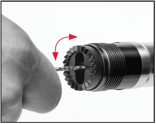
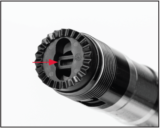
Use a key or small screwdriver to press in on the three-shot adaptor (plug), then rotate a quarter-turn.
Figure 9
Figure 9
Remove the three-shot adaptor (plug).
The Maxus II is delivered with the magazine three-shot adaptor (plug) installed in the magazine, limiting magazine capacity to two shells in compliance with federal migratory bird regulations. If you do not wish to be limited to three shots, when it is not required by law, you can remove (or reinstall) the three-shot adaptor as follows:
REMOVING THE THREE-SHOT ADAPTOR (PLUG)
1. Lock the bolt rearward by pulling the bolt handle fully to the rear.
NEVER ALLOW THE ACTION TO SLAM CLOSED BY PRESSING THE BOLT RELEASE BUTTON WITHOUT THE BARREL INSTALLED. IF THE SLIDE ASSEMBLY IS RELEASED FORWARD WITH THE BARREL REMOVED, THE BOLT HANDLE WILL STRIKE THE RECEIVER AND CAUSE DAMAGE.
2. Remove the forearm as explained previously.
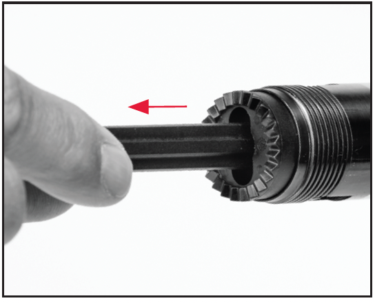
3. The Maxus II features the unique TurnKey Magazine Plug which is quickly and easily removed by inserting a key or standard screwdriver into the slot in the end of the magazine tube. To remove the three-shot adaptor (plug), press inward and turn the key or flat-blade screwdriver a quarter-turn to align the three-shot adaptor (plug) with the slot in the end of the magazine (Figure 8). This unlocks the three-shot adaptor (plug), allowing it to be removed.
4. If the barrel and forearm are on the shotgun, hold them to prevent them from falling out of the receiver while pointing the magazine tube down to allow the three-shot adaptor (plug) to fall out of the end of the magazine tube. Grasp and remove it (Figure 9).
5. Reinstall the gas piston, barrel, forearm and magazine cap.
INSTALLING THE THREE-SHOT ADAPTOR (PLUG)
If you need to install the magazine three-shot adaptor (plug) to limit the magazine to two shells, again perform the following operation:
1. Lock the bolt rearward by pulling the bolt handle fully to the rear.
NEVER ALLOW THE ACTION TO SLAM CLOSED BY PRESSING THE BOLT RELEASE BUTTON WITHOUT THE BARREL INSTALLED. IF THE SLIDE ASSEMBLY IS RELEASED FORWARD WITH THE BARREL REMOVED, THE BOLT HANDLE WILL STRIKE THE RECEIVER AND CAUSE DAMAGE.
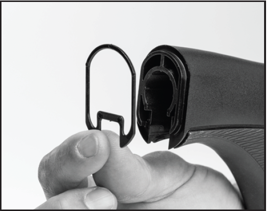
Figure 10
Figure 10
The three-shot adaptor shown secured in the magazine tube.
2. Remove the forearm as explained previously.
3. Insert the magazine three-shot adaptor into the slot in the end of the magazine tube.
4. Insert a key or flat-blade screwdriver into the slot in the end of the magazine tube. Press inward and turn the three-shot adaptor (plug) a quarter-turn to secure in the magazine (Figure 10).
5. Reinstall the gas piston, barrel, forearm and magazine cap.
LOADING
WHEN LOADING YOUR SHOTGUN ALWAYS KEEP THE MUZZLE POINTED IN A SAFE DIRECTION, ALWAYS PLACE THE “SAFETY” IN THE ON SAFE POSITION AND KEEP YOUR FINGERS AWAY FROM THE TRIGGER. FAILURE TO FOLLOW THESE WARNINGS COULD RESULT IN SERIOUS INJURY OR DEATH.
WHEN LOADING YOUR SHOTGUN ALWAYS KEEP THE MUZZLE POINTED IN A SAFE DIRECTION, ALWAYS PLACE THE “SAFETY” IN THE ON SAFE POSITION AND KEEP YOUR FINGERS AWAY FROM THE TRIGGER. FAILURE TO FOLLOW THESE WARNINGS COULD RESULT IN SERIOUS INJURY OR DEATH.
DO NOT CARRY YOUR SHOTGUN WITH A SHELL IN THE CHAMBER TO AVOID ACCIDENTAL DISCHARGE. WHEN FIRING IS NO LONGER IMMINENT, MAKE SURE THE “SAFETY” IS IN THE ON SAFE POSITION AND UNLOAD THE CHAMBER. FAILURE TO FOLLOW THESE WARNINGS COULD RESULT IN SERIOUS INJURY OR DEATH.
DO NOT CARRY YOUR SHOTGUN WITH A SHELL IN THE CHAMBER TO AVOID ACCIDENTAL DISCHARGE. WHEN FIRING IS NO LONGER IMMINENT, MAKE SURE THE “SAFETY” IS IN THE ON SAFE POSITION AND UNLOAD THE CHAMBER. FAILURE TO FOLLOW THESE WARNINGS COULD RESULT IN SERIOUS INJURY OR DEATH.
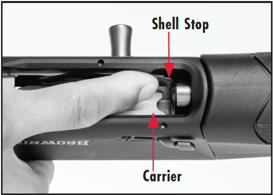
ALWAYS TAKE CARE WHEN LOADING THE MAGAZINE. THE EDGES OF THE CARRIER ARE SHARP AND MAY CAUSE INJURY TO FINGERS OR DAMAGE GLOVES.
ALWAYS TAKE CARE WHEN LOADING THE MAGAZINE. THE EDGES OF THE CARRIER ARE SHARP AND MAY CAUSE INJURY TO FINGERS OR DAMAGE GLOVES.
Figure 11
Figure 11
Insert the shell into the bottom of the receiver and push it fully forward into the magazine.
LOADING THE MAGAZINE
1. Pull the bolt handle to the rear until the bolt locks in the open position. Visually inspect the chamber, feed mechanism and magazine to make sure they are unloaded and clear of any obstructions.
2. Close the bolt by pressing the bolt release button.
3. Insert a shell of the proper gauge and length through the loading port at the bottom of the receiver up into the magazine, using your thumb to position it fully forward in the magazine tube (Figure 11). Make certain the rim of the shell engages the shell stop and is held fully inside the magazine tube. It will make an audible click when fully inserted.
4. If desired, continue loading the magazine until it is full.
LOADING THE CHAMBER MANUALLY FROM THE MAGAZINE
1. With the bolt closed, depress the carrier with the front of the shell and, using your thumb, push the shell into the magazine until the shell is held in place by the shell stop.
2. If desired, continue to load the magazine, as explained above, to full capacity.
3. If shooting is imminent, a shell can now be moved from the magazine to the chamber by pulling back fully on the bolt handle and releasing it forward. A shell will be fed automatically from the magazine to the chamber as the bolt closes. Another shell can then be inserted into the magazine to load to full capacity
Figure 12
Figure 12
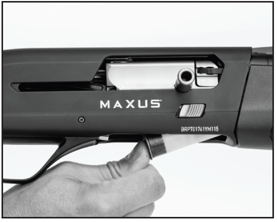
Insert a shell through the ejection port into the breech.
THE SHOTGUN IS NOW READY TO FIRE BY SIMPLY MOVING THE “SAFETY” TO THE OFF SAFE POSITION AND PULLING THE TRIGGER.
THE SHOTGUN IS NOW READY TO FIRE BY SIMPLY MOVING THE “SAFETY” TO THE OFF SAFE POSITION AND PULLING THE TRIGGER.
LOADING THE CHAMBER THROUGH THE EJECTION PORT
1. Pull the bolt handle to the rear until the bolt locks in the open position. Visually inspect the chamber, feed mechanism and magazine to make sure they are clear of any obstructions.
2. If shooting is imminent, insert a shell of the proper gauge and length through the ejection port into the open breech (Figure 12).
3. Press the bolt release button to deliver the shell into the chamber.
4. With a shell in the chamber, you may load the magazine to full capacity. To load the magazine, insert a shell of proper gauge and length through the loading port at the bottom of the receiver up into the magazine, using your thumb to position it fully forward in the magazine tube. Make sure the rim of the shell engages the shell stop and is held fully inside the magazine tube. It will make an audible click when fully inserted.
Figure 13
Figure 13
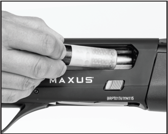
Insert the shell into the bottom of the receiver and push it fully forward into the magazine.
THE SHOTGUN IS NOW READY TO FIRE BY SIMPLY MOVING THE “SAFETY” TO THE OFF SAFE POSITION AND PULLING THE TRIGGER.
THE SHOTGUN IS NOW READY TO FIRE BY SIMPLY MOVING THE “SAFETY” TO THE OFF SAFE POSITION AND PULLING THE TRIGGER.
KEEP YOUR FINGERS CLEAR OF THE EJECTION PORT WHEN LOADING THE SHOTGUN USING THE SPEED LOADING PROCEDURE. FAILURE TO FOLLOW THIS WARNING COULD RESULT IN INJURY.
KEEP YOUR FINGERS CLEAR OF THE EJECTION PORT WHEN LOADING THE SHOTGUN USING THE SPEED LOADING PROCEDURE. FAILURE TO FOLLOW THIS WARNING COULD RESULT IN INJURY.
SPEED LOADING
The Speed Load function makes loading the chamber fast and convenient. With the bolt open and the magazine empty, the first shell inserted into the magazine will be instantly loaded into the chamber. To use this feature, perform the following operation.
1. If shooting is imminent, lock the bolt open.
2. Insert a shell into the magazine (Figure 13). The shell will be automatically cycled from the magazine to the chamber.
KEEP YOUR FINGERS CLEAR OF THE EJECTION PORT WHEN LOADING THE SHOTGUN USING THE SPEED LOADING PROCEDURE. FAILURE TO FOLLOW THIS WARNING COULD RESULT IN INJURY.
KEEP YOUR FINGERS CLEAR OF THE EJECTION PORT WHEN LOADING THE SHOTGUN USING THE SPEED LOADING PROCEDURE. FAILURE TO FOLLOW THIS WARNING COULD RESULT IN INJURY.
3. If desired, load the magazine to full capacity by inserting additional shells of proper gauge and length through the loading port at the bottom of the receiver up into the magazine, using your thumb to position it fully forward in the magazine tube. Make sure the rim of the shell engages the shell stop and is held fully inside the magazine tube. It will make an audible click when fully inserted.
THE SHOTGUN IS NOW READY TO FIRE BY SIMPLY MOVING THE “SAFETY” TO THE OFF SAFE POSITION AND PULLING THE TRIGGER.
THE SHOTGUN IS NOW READY TO FIRE BY SIMPLY MOVING THE “SAFETY” TO THE OFF SAFE POSITION AND PULLING THE TRIGGER.
FIRING
FIRING
NEVER LOAD A SHELL INTO THE CHAMBER OR PLACE THE “SAFETY” IN THE OFF SAFE POSITION UNLESS SHOOTING IS IMMINENT. ALWAYS KEEP THE MUZZLE POINTED IN A SAFE DIRECTION. FAILURE TO FOLLOW THESE WARNINGS COULD RESULT IN SERIOUS INJURY OR DEATH.
NEVER LOAD A SHELL INTO THE CHAMBER OR PLACE THE “SAFETY” IN THE OFF SAFE POSITION UNLESS SHOOTING IS IMMINENT. ALWAYS KEEP THE MUZZLE POINTED IN A SAFE DIRECTION. FAILURE TO FOLLOW THESE WARNINGS COULD RESULT IN SERIOUS INJURY OR DEATH.
1. Place the “safety” in the on safe position.
2. Load a shell into the chamber as explained previously.
3. With a shell in the chamber, you need only move the “safety” to the off safe position to fire the shotgun.
4. When ready to fire, move the “safety” into the off safe position, take aim and squeeze the trigger.
After a shell is fired, the gas system operates the bolt, ejects the fired shell, picks up a loaded shell from the magazine and automatically chambers it. You may continue to fire the shotgun until the magazine is empty by pulling the trigger to fire each shell. After the last shell is fired, the breech of the shotgun remains open, with the bolt locked to the rear. This allows convenient and fast reloading.
If you are done shooting, leave the bolt locked to the rear, with the breech in the open position so that you may visually inspect the chamber, bore, carrier and magazine to be sure they contain no shells.
AFTER FIRING, OR WHEN SHOOTING IS NO LONGER IMMINENT, IMMEDIATELY PLACE THE “SAFETY” IN THE ON SAFE POSITION. FAILURE TO FOLLOW THESE WARNINGS COULD RESULT IN SERIOUS INJURY OR DEATH.
AFTER FIRING, OR WHEN SHOOTING IS NO LONGER IMMINENT, IMMEDIATELY PLACE THE “SAFETY” IN THE ON SAFE POSITION. FAILURE TO FOLLOW THESE WARNINGS COULD RESULT IN SERIOUS INJURY OR DEATH.
EVEN WITH BOLT LOCKED OPEN AFTER SHOOTING, DO NOT ASSUME THE SHOTGUN IS UNLOADED. ALWAYS INSPECT THE CHAMBER, BARREL, FEED MECHANISM AND MAGAZINE TO BE CERTAIN THE SHOTGUN IS COMPLETELY UNLOADED. FAILURE TO FOLLOW THESE WARNINGS COULD RESULT IN SERIOUS INJURY OR DEATH.
EVEN WITH BOLT LOCKED OPEN AFTER SHOOTING, DO NOT ASSUME THE SHOTGUN IS UNLOADED. ALWAYS INSPECT THE CHAMBER, BARREL, FEED MECHANISM AND MAGAZINE TO BE CERTAIN THE SHOTGUN IS COMPLETELY UNLOADED. FAILURE TO FOLLOW THESE WARNINGS COULD RESULT IN SERIOUS INJURY OR DEATH.
UNLOADING
WHEN UNLOADING YOUR SHOTGUN ALWAYS PLACE THE “SAFETY” IN THE ON SAFE POSITION. KEEP THE MUZZLE POINTED IN A SAFE DIRECTION AND YOUR FINGERS AWAY FROM THE TRIGGER. FAILURE TO FOLLOW THESE WARNINGS COULD RESULT IN SERIOUS INJURY OR DEATH.
WHEN UNLOADING YOUR SHOTGUN ALWAYS PLACE THE “SAFETY” IN THE ON SAFE POSITION. KEEP THE MUZZLE POINTED IN A SAFE DIRECTION AND YOUR FINGERS AWAY FROM THE TRIGGER. FAILURE TO FOLLOW THESE WARNINGS COULD RESULT IN SERIOUS INJURY OR DEATH.
ALWAYS INSPECT THE CHAMBER, BARREL, FEED MECHANISM AND MAGAZINE CAREFULLY AFTER UNLOADING TO BE SURE ALL LIVE SHELLS ARE CLEARED FROM THE FIREARM.
ALWAYS INSPECT THE CHAMBER, BARREL, FEED MECHANISM AND MAGAZINE CAREFULLY AFTER UNLOADING TO BE SURE ALL LIVE SHELLS ARE CLEARED FROM THE FIREARM.
Figure 14
Figure 14
Push inward on the shell stop to unload the magazine.
Speed Unloading
1. With the “safety” in the on safe position, turn the shotgun over so the trigger guard is facing up, then depress the carrier with your finger as far as it will go.
2. Shells are retained in the magazine by the shell stop that catches the rim of the shell base. Locate the shell stop inside the receiver on the right side of the loading port (visually to the left side when looking down into the loading port).
3. Push inward on the shell stop with your index finger (Figure 14) to release a shell from the magazine. As the shell stop is pressed in, a shell will be forced out of the magazine under spring pressure. Catch the shell in your hand as it comes out.
4. Press the stop again to release the next shell. Continue to do this until the magazine is empty. Be careful not to pinch your finger.
5. With the “safety” still in the on safe position, pull rearward on the bolt handle to eject the shell from the chamber. The bolt will lock rearward when the action is cycled with an empty magazine.
6. Using your index finger, feel the opening of the magazine to make sure there are no shells that have not been fed from the magazine and ejected. Visually inspect the chamber, feed mechanism and magazine to ensure there are no shells remaining.
Unloading by Cycling the Action
1. With the “safety” in the on safe position, grasp the bolt handle and cycle the action until all shells are transferred from the magazine to the chamber and then ejected. Take care to avoid damaging shells. Avoid letting them fall to the ground.
2. When the last shell in the magazine has been cycled through the chamber and out the ejection port, the bolt will lock rearward. The bolt will lock rearward when cycled with an empty magazine.
3. Using your index finger, feel the opening of the magazine to make sure there are no shells that have not been fed from the magazine and ejected. Visually inspect the chamber, feed mechanism and magazine to ensure there are no shells remaining.
MAGAZINE CUT-OFF
Figure 15
Figure 15
Pull the Magazine Cut-Off rearward to block the magazine.
WHEN UNLOADING YOUR SHOTGUN ALWAYS PLACE THE “SAFETY” IN THE ON SAFE POSITION. KEEP THE MUZZLE POINTED IN A SAFE DIRECTION AND YOUR FINGERS AWAY FROM THE TRIGGER. FAILURE TO FOLLOW THESE WARNINGS COULD RESULT IN SERIOUS INJURY OR DEATH.
WHEN UNLOADING YOUR SHOTGUN ALWAYS PLACE THE “SAFETY” IN THE ON SAFE POSITION. KEEP THE MUZZLE POINTED IN A SAFE DIRECTION AND YOUR FINGERS AWAY FROM THE TRIGGER. FAILURE TO FOLLOW THESE WARNINGS COULD RESULT IN SERIOUS INJURY OR DEATH.
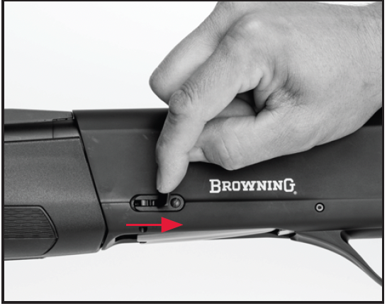
The Magazine Cut-Off allows you to unload a shell from the chamber without cycling a shell from the magazine. With this feature you can quickly and easily load a heavier or lighter shell into the chamber should the need arise. To change loads in the chamber using the Magazine Cut-Off, perform the following operation:
1. Pull the Magazine Cut-Off lever to the rear to engage the Magazine Cut-Off and block the magazine (Figure 15). With the lever to the rear, shells are locked in the magazine. Additionally, shells cannot be loaded into the magazine with the lever to the rear.
2. Pull the bolt handle fully rearward to eject the shell in the chamber.
3. Load a shell through the ejection port.
THE SHOTGUN IS NOW READY TO FIRE BY SIMPLY MOVING THE “SAFETY” TO THE OFF SAFE POSITION AND PULLING THE TRIGGER.
THE SHOTGUN IS NOW READY TO FIRE BY SIMPLY MOVING THE “SAFETY” TO THE OFF SAFE POSITION AND PULLING THE TRIGGER.
Figure 16
Figure 16
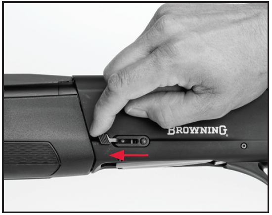
Push the Magazine Cut-Off forward to unblock the magazine.
4. The shotgun may now be fired as explained previously, and will fire only the shell in the chamber. Any shells in the magazine will be retained by the Magazine Cut-Off until it is manually disengaged. The bolt will also lock to the rear when fired while the Magazine Cut-Off is engaged.
5. To disengage the Magazine Cut-Off, place the "safety" in the on safe position, then push the Magazine Cut-Off lever fully forward (Figure 16). If the action is open, a shell will immediately feed from the magazine. If the action is closed, a shell can be loaded into the chamber from the magazine as explained.
INTERCHANGEABLE CHOKE TUBE SYTEM
INTERCHANGEABLE CHOKE TUBE SYTEM
NEVER ATTEMPT TO REMOVE OR INSTALL A CHOKE TUBE IN A LOADED FIREARM. WHENEVER REMOVING OR INSTALLING A CHOKE TUBE IN A SHOTGUN ALWAYS KEEP THE MUZZLE POINTED IN A SAFE DIRECTION. OPEN THE ACTION AND MAKE ABSOLUTELY CERTAIN THE SHOTGUN IS COMPLETELY UNLOADED, ALWAYS PLACE THE “SAFETY” IN THE ON SAFE POSITION AND KEEP YOUR FINGERS AWAY FROM THE TRIGGER. FAILURE TO FOLLOW THESE WARNINGS COULD RESULT IN SERIOUS INJURY OR DEATH.
NEVER ATTEMPT TO REMOVE OR INSTALL A CHOKE TUBE IN A LOADED FIREARM. WHENEVER REMOVING OR INSTALLING A CHOKE TUBE IN A SHOTGUN ALWAYS KEEP THE MUZZLE POINTED IN A SAFE DIRECTION. OPEN THE ACTION AND MAKE ABSOLUTELY CERTAIN THE SHOTGUN IS COMPLETELY UNLOADED, ALWAYS PLACE THE “SAFETY” IN THE ON SAFE POSITION AND KEEP YOUR FINGERS AWAY FROM THE TRIGGER. FAILURE TO FOLLOW THESE WARNINGS COULD RESULT IN SERIOUS INJURY OR DEATH.

BROWNING INVECTOR-DS CHOKE TUBES ARE FOR USE ONLY IN BROWNING SHOTGUNS WITH BACK-BORED BARRELS, AND ARE NOT INTERCHANGEABLE WITH BROWNING STANDARD INVECTOR OR INVECTOR-PLUS CHOKE TUBES. DO NOT USE INVECTOR-DS TUBES IN BARRELS THREADED FOR INVECTOR-PLUS OR STANDARD INVECTOR TUBES. DO NOT USE BROWNING INVECTOR-DS, STANDARD INVECTOR OR INVECTOR-PLUS CHOKE TUBES IN ANY SHOTGUN BARRELS NOT SUPPLIED BY BROWNING. DO NOT USE ANY OTHER CHOKING DEVICE IN ANY SHOTGUN BARREL SUPPLIED BY BROWNING.
USE ONLY THE APPROPRIATE GAUGE OF INVECTOR-DS CHOKE TUBE IN THIS SHOTGUN. DO NOT FIRE THIS SHOTGUN WITHOUT THE CORRECT CHOKE TUBE INSTALLED. DAMAGE MAY RESULT TO THE THREADS INSIDE THE BARREL.
FAILURE TO FOLLOW THIS INFORMATION COULD RESULT IN DAMAGE TO YOUR SHOTGUN OR POSSIBLE INJURY.
Figure 17
Figure 17
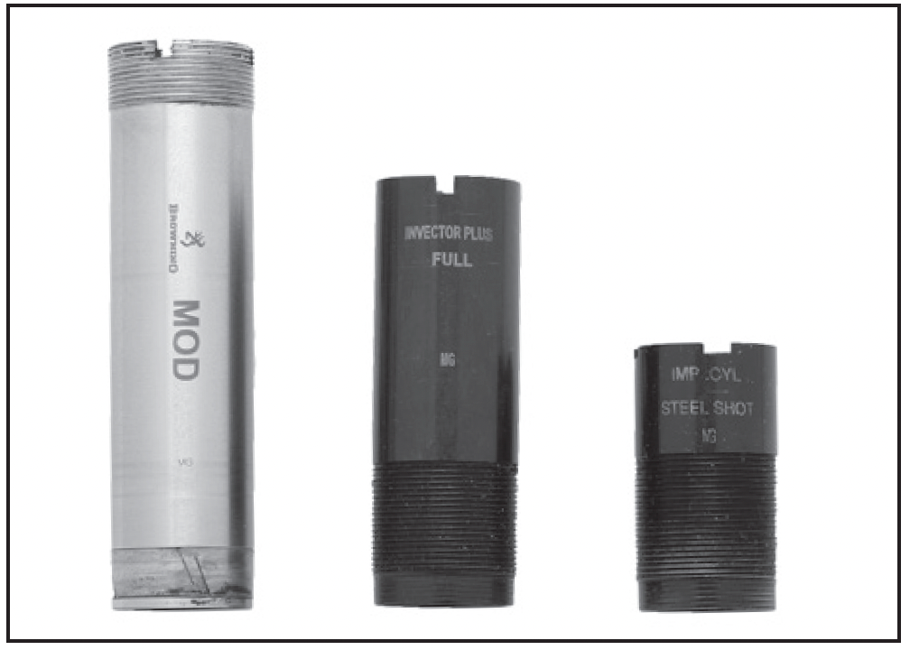
Left: Invector-DS
Center: Invector-Plus
Right: Standard Invector
Use only the Invector-DS choke tube T-Wrench supplied with your shotgun to install and remove Invector-DS choke tubes. Using any other wrench may damage the threads in the barrel.
Maxus II shotgun barrels are threaded to accept the Invector-DS choke system. Confirm the choke system of your shotgun by looking on the right side of the barrel where the specifications are inscribed. Invector choke tubes are identified in Figure 17 (flush mount tubes are shown).
The constriction of each choke tube is indicated twice on the choke tube: On the side of the tube, and indicated with a “notch” code on the top rim of the tube. The included choke tube T-Wrench is used to remove and install choke tubes.
Some target shotguns include premium extended choke tubes. The constriction of premium choke tubes is indicated twice on the choke tube: On the side of the tube, and indicated with an abbreviation in he colored band. The constriction of flush fit choke tubes is indicated twice on the choke tube: On the side of the tube, and indicated with a “notch” code on the top rim of the tube.
The included choke tube T-Wrench is used to remove and install
choke tubes.
Invector choke tubes are compatible with factory ammunition that has been loaded in compliance with SAAMI specifications, including magnum lead and steel shot loads, sabots and shotgun slug loads.
Replacement and additional tubes and wrenches are available from your Browning dealer, or by contacting our Consumer Department. See “Service or Repair” on page 56 for contact information.
CHOKE TUBE SELECTION
To help you choose the correct choke tube for each hunting and shooting situation, all Browning Invector choke tubes are inscribed on the side with the patterns they produce with both lead and steel shot. Each Invector tube also has notches in the top rim of the tube (Figure 18). These notches are a code to identify the choke designation while the tube is installed. Rim notches refer specifically to lead shot. Use the chart to cross-reference from lead to steel, and determine the appropriate tubes for your ammunition and hunting/shooting situation.
Several choke tubes are supplied with your shotgun. The choke tubes listed are also available as accessories. Remember, Standard Invector, Invector-Plus and Invector-DS tubes are not interchangeable.
Invector-Plus and Invector-DS tubes are for Browning shotguns with back-bored barrels only. Before removing or installing tubes, or reading the rim notch code, make sure the shotgun is fully unloaded.
CHOKE TUBE REMOVAL
1. Place the “safety” in the on safe position. Always make sure the shotgun is completely unloaded. Keep the muzzle pointed in a safe direction.
Figure 18
Figure 18
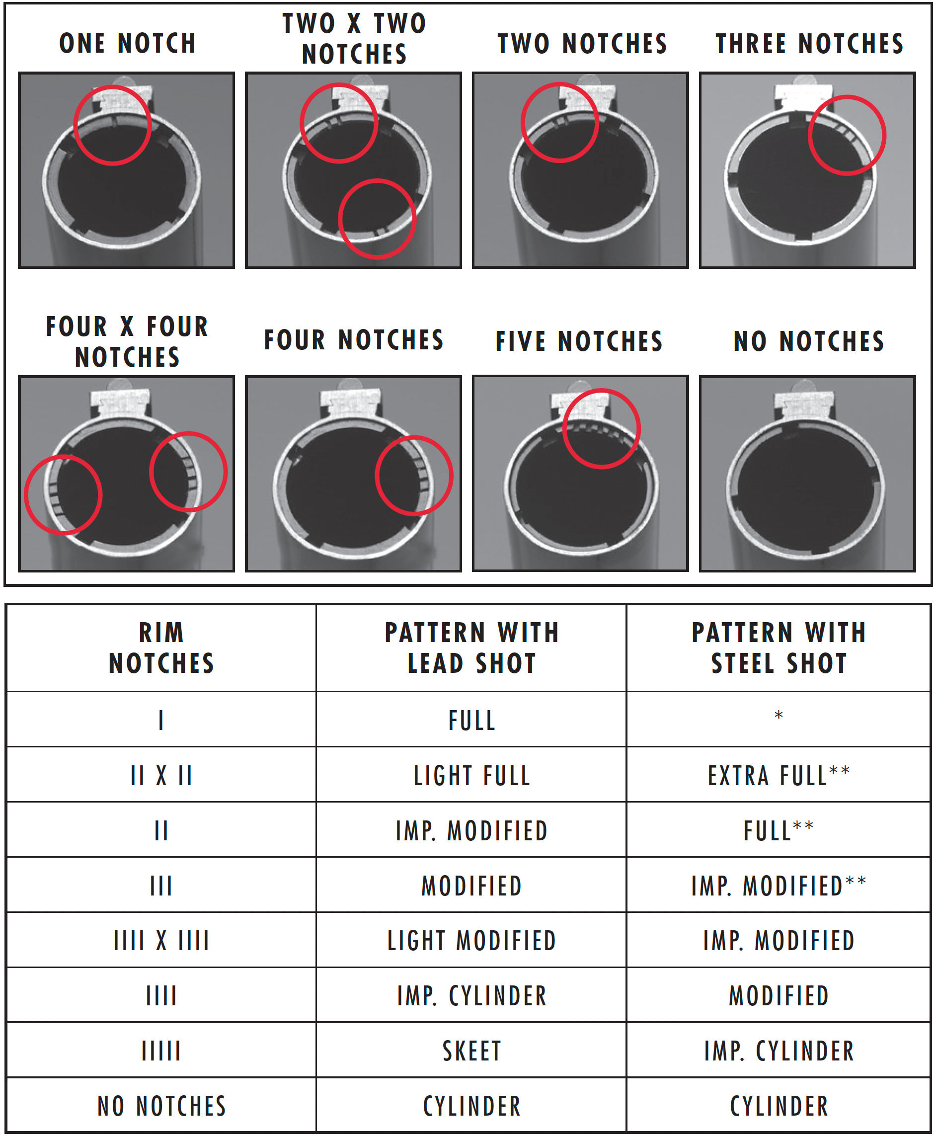
* Not for use with steel shot. Using an over-tight choke constriction with steel shot will result in an ineffective “blown” pattern.
** When more than one choke designation is listed for a given steel shot pattern, use the more open choke listed for high velocity, larger shot size steel loads.
2. Use the choke tube T-Wrench to loosen the tube, turning it counterclockwise (Figure 21). Finger-twist the tube the rest of the way out of the barrel.
Figure 19
Figure 19
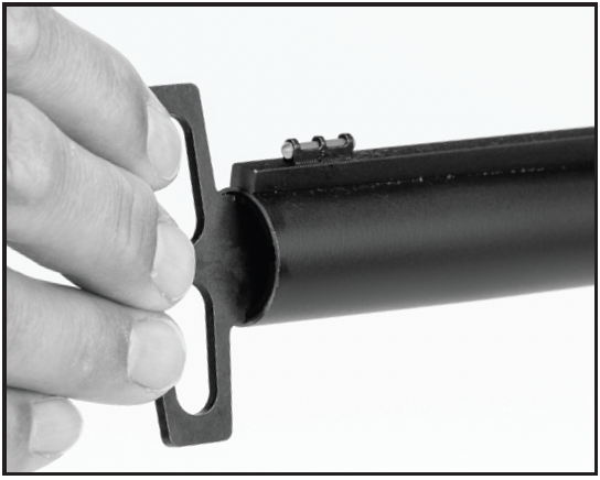
Use the choke tube T-Wrench to remove and install the choke tube in the barrel.
FAILURE TO CLEAN AND OIL THE THREADS ON THE CHOKE TUBE COULD RESULT IN THE CHOKE TUBE SEIZING IN THE BARREL.
CHOKE TUBE INSTALLATION
1. Place the “safety” in the on safe position. Always make sure the shotgun is completely unloaded. Keep the muzzle pointed in a safe direction.
2. Before installing a tube, check the choke tube threads in the muzzle, as well as the threads on the choke tube to be sure they are clean. If dirty, clean the tube with a nylon brush and gun solvent. Lightly oil the choke tube and threads with a high-quality, lightweight gun oil.
3. Using your fingers, screw the appropriate tube into the muzzle end of the barrel, threaded end outward. When it becomes finger-tight, use the choke tube T-Wrench to firmly seat the tube.
The choke tube should be periodically checked to assure that it is tight and firmly seated. Before checking, follow all the choke tube removal and installation safety guidelines previously outlined.
Adjusting Length of Pull
The stock of Maxus II can be adjusted for length of pull by adding or removing spacers to the rear of the stock.Two spacer sizes are available: ¼" and ½" . A maximum of ½" of spacers can be added with the screws provided. A maximum of ¾" of spacers can be used, however, the top screw will need to be replaced.
If longer or shorter screws are required, commonly found M4x0.7mm Pan Head Phillips screws of the necessary length are the recommended replacement screws. Spacers can be ordered through your Browning dealer or by calling our Customer Service Department at (800) 322-4626.
Figure 20
Figure 20
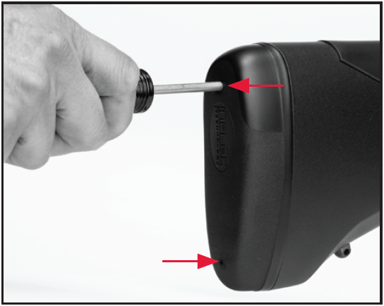
Insert a screwdriver into the holes in the recoil pad.
Figure 21
Figure 21
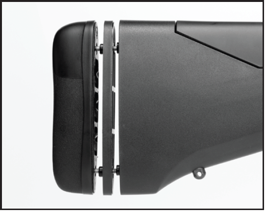
Install or remove stock spacers to achieve correct length of pull.
BEFORE PERFORMING ADJUSTMENT PROCEDURES, PLACE THE “SAFETY” IN THE ON SAFE POSITION. OPEN THE ACTION AND MAKE CERTAIN YOUR SHOTGUN IS COMPLETELY UNLOADED. KEEP THE MUZZLE POINTED IN A SAFE DIRECTION. FAILURE TO FOLLOW THESE WARNINGS COULD RESULT IN SERIOUS INJURY OR DEATH.
BEFORE PERFORMING ADJUSTMENT PROCEDURES, PLACE THE “SAFETY” IN THE ON SAFE POSITION. OPEN THE ACTION AND MAKE CERTAIN YOUR SHOTGUN IS COMPLETELY UNLOADED. KEEP THE MUZZLE POINTED IN A SAFE DIRECTION. FAILURE TO FOLLOW THESE WARNINGS COULD RESULT IN SERIOUS INJURY OR DEATH.
Adjusting length of pull
1. Use a #2 cross tip or Phillips screwdriver to remove the recoil pad at the end of the buttstock (Figure 20). Place a small amount of petroleum jelly on the screw access slits on the top and bottom of the rear of the buttstock to prevent damaging the recoil pad. Insert the screwdriver into each of the two access holes. Make sure the tip of the screwdriver engages the head of the screw. Turn the screw counterclockwise until the screw is completely loose from the stock. When both screws are free, remove the recoil pad.
2. Add or subtract spacers to fit your firearm to your specifications (Figure 21). After making an adjustment hold the shotgun to your shoulder to determine if the new length feels comfortable. Remember to always keep the muzzle pointed in a safe direction, with the “safety” in the on safe position and make certain the shotgun is completely unloaded.
3. When you are satisfied with the length of pull, start the screws through the pad and spacer(s) into the holes in the stock.
4. Attach the recoil pad to the stock using the screwdriver. Turn the screws clockwise to tighten. Do not overtighten the screws.
Figure 22
Figure 22
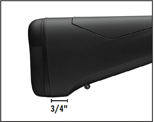
The composite stock can be trimmed a maximum of 3/4".
INSTALL THE LONGER SCREW IN THE TOP HOLE OF THE RECOIL PAD. INSTALLING THE LONG SCREW IN THE BOTTOM HOLE WILL DAMAGE THE STOCK.
TRIMMING THE STOCK
We recommend contacting a professional gunsmith if a shorter length of pull is required. Wood stock models require cutting the stock and replacing and fitting a new recoil pad. Composite stock models that include the integrated sling swivel eyelet (Figure 22) can be trimmed a maximum of ." and the Inflex recoil pad reinstalled using shorter screws (not provided). The length of the screws will be determined by the amount of material removed from the stock.
Adjusting Cast and Drop at Comb
BEFORE PERFORMING ADJUSTMENT PROCEDURES, PLACE THE “SAFETY” IN THE ON SAFE POSITION. OPEN THE ACTION AND MAKE CERTAIN YOUR SHOTGUN IS COMPLETELY UNLOADED. KEEP THE MUZZLE POINTED IN A SAFE DIRECTION. FAILURE TO FOLLOW THESE WARNINGS COULD RESULT IN SERIOUS INJURY OR DEATH.
BEFORE PERFORMING ADJUSTMENT PROCEDURES, PLACE THE “SAFETY” IN THE ON SAFE POSITION. OPEN THE ACTION AND MAKE CERTAIN YOUR SHOTGUN IS COMPLETELY UNLOADED. KEEP THE MUZZLE POINTED IN A SAFE DIRECTION. FAILURE TO FOLLOW THESE WARNINGS COULD RESULT IN SERIOUS INJURY OR DEATH.
Figure 23
Figure 23
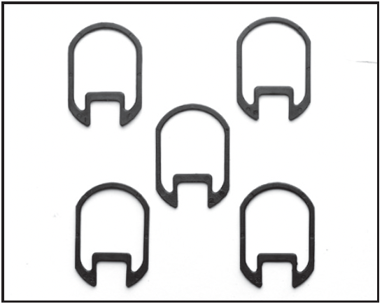
Cast and drop adjustment shims. Shim 2 is installed on your shotgun and is not shown.
Six shims are included with your new shotgun (Figure 25). The shims fit between the buttstock and receiver, allowing customized adjustments to the comb and heel. Each shim is labeled/stamped for a specific amount of adjustment. The neutral shim, No. 2, is already installed on your shotgun.
Drop at comb is defined as the place on the comb that your cheek rests when taking aim. If drop at comb is correct, your eye naturally falls in line with the sight.
Shims marked 1, 2 and 3 do not give any cast on or off. The stock remains straight. They only adjust drop at comb.
These shims with their respective stamps are further clarified here:
• Shim 1 raises the comb approximately 1/16", and the heel approximately 1/8".
• Shim 2 is neutral. This shim is already installed on the firearm.
• Shim 3 lowers the comb approximately 1/16", and the heel approximately 1/8".
Some right-handed shooters like the stock to angle away (cast off) from their face, making their line of sight more directly in line with the barrel. Angling the stock to the left for left-handed shooters is “cast on.” Shims marked 1R1L, 2R2L, and 3R3L, will all adjust drop at comb the same amount as shims 1, 2 and 3, and will also adjust the cast right or left approximately 1/8". You will notice that the two opposing edges of these spacers are different in thickness. For right-handed shooters, install shims between the receiver and the stock with the R facing the end of the buttstock, so its thicker side is on the left side. This casts the stock slightly to the right, away from the face of a right-handed shooter. If you turn the shim around so the L is facing the end of the buttstock, and it will cast the stock to the left. These shims with their respective stamps are further clarified here:
• Shim 1R1L raises the comb approximately 1/16", and the heel approximately 1/8" and will adjust the cast on or cast off
approximately 1/8".
• Shim 2R2L adds the same amount of cast to the stock as shim 1R1L with neutral drop like shim 2.
• Shim 3R3L adds the same amount of cast to the stock as shims 1R1L and 2R2L, and lowers the comb approximately 1/16" and the heel approximately 1/8".
INSTALLING A SHIM
IMPORTANT: Before loosening the buttstock to install shims, the trigger group should be in position in the receiver. This aligns the buttstock and makes assembly easier.
1. Make sure your shotgun is completely unloaded and the “safety” is in the on safe position.
2. Use a #2 cross tip or Phillips screwdriver to remove the recoil pad from the buttstock (Figure 20.) Place a small amount of petroleum jelly on the screw access slits on the top and bottom of the rear of the buttstock to prevent damaging the recoil pad. Insert the screwdriver into each of the two access holes. Make certain the tip of the screwdriver engages the head of the screw. Turn the screw counterclockwise until the screw is completely loose from the stock. When both screws are free, remove the recoil pad.
Figure 24
Figure 24
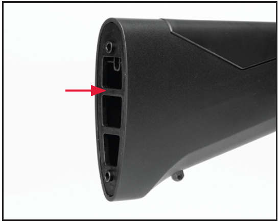
Remove the stock insert.
Figure 25
Figure 25
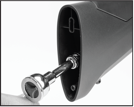
Install or remove stock spacers to achieve correct length of pull.
3. Remove the stock insert to access the stock bolt nut (Figure 24).
4. Use a ½" socket wrench to remove the stock bolt nut and stock bolt washer. (Figure 25).
5. Completely remove the buttstock from the receiver, along with the existing shim, and install the shim you have selected (Figure 26). Make certain you have the proper shim installed and in position before reattaching the buttstock and recoil pad.
6. When you are satisfied with the fit, reattach the buttstock to the receiver with the washer and the nuts.
7. Torque the nut to 50in/lb, do not over-tighten.
8. Reinstall the stock insert.
9. Reinstall the recoil pad with care, so as not to scratch or mar the finish of the stock.
Figure 26
Figure 26
Install the shim between the stock and receiver.
INSTALLING A SCOPE OR OPTICS
BEFORE MOUNTING A SCOPE, SIGHT OR OTHER ACCESSORIES ON YOUR SHOTGUN, PLACE THE “SAFETY” IN THE ON SAFE POSITION. OPEN THE ACTION AND MAKE CERTAIN YOUR SHOTGUN IS COMPLETELY UNLOADED. KEEP THE MUZZLE POINTED IN A SAFE DIRECTION. FAILURE TO FOLLOW THESE WARNINGS COULD RESULT IN SERIOUS INJURY OR DEATH.
BEFORE MOUNTING A SCOPE, SIGHT OR OTHER ACCESSORIES ON YOUR SHOTGUN, PLACE THE “SAFETY” IN THE ON SAFE POSITION. OPEN THE ACTION AND MAKE CERTAIN YOUR SHOTGUN IS COMPLETELY UNLOADED. KEEP THE MUZZLE POINTED IN A SAFE DIRECTION. FAILURE TO FOLLOW THESE WARNINGS COULD RESULT IN SERIOUS INJURY OR DEATH.
Some Maxus II shotguns are designed to accept a scope or other optical sight; usually these are turkey and deer models. The receivers of some of these models are drilled and tapped for scope bases, while other models are equipped with a cantilever scope base. If your shotgun has a cantilever scope base, follow the mounting instructions supplied with your scope rings and/or scope. If your shotgun’s receiver is drilled and tapped for scope mounts, three holes (in line on top of the receiver) will be visible. They are fitted with filler screws. If your shotgun is drilled and tapped, adhere to the following:
YOUR SHOTGUN IS DRILLED AND TAPPED FOR THE MOUNTING OF BASES AND RINGS TO ACCOMMODATE AN APPROPRIATE SCOPE OR SIGHT. ALWAYS USE THE CORRECT BASES FOR THIS SHOTGUN WITH THE APPROPRIATE LENGTH SCREWS WHICH ARE AT LEAST 11/32" IN LENGTH.
1. Place your shotgun on a table or other safe/secure location. Protect the finish with rags or other padding.
2. You should have a compatible one-piece style base and three screws of at least 11/32" in length.
3. Clean all oil, grease or dirt from the receiver top and from the scope base parts.
4. Position your shotgun in the horizontal position with the top of the receiver upward.
5. Remove all three filler screws from the top of the receiver using a very small, thin-bladed gunsmithing-type screwdriver.
6. Pre-position the base on the receiver top to determine the best orientation of the base. Most bases have transverse grooves cut into them that are offset from the middle. These are the grooves that the crossbolts in your scope rings will pass through. The grooves are offset to allow you to position the bases to fit the design/length of your scope and the placement of the scope, front to rear for proper eye relief. Place both grooves to the rear, both to the front, or one in each direction, depending on the desired position of your scope.
7. Once you know which configuration you will use, insert the screws through the base and screw it into the receiver top using the
correct wrench or screwdriver (usually a 3/32" hex wrench). You must use screws which are at least 11/32" in length to ensure proper thread engagement. Once the bases are installed, check inside the receiver to verify that the base mounting screws are not too long and interfering with the operation of the bolt. Many gunsmiths find it helpful to use a drop of serviceable blue thread locking compound to ensure the screws stay tight. Make sure the thread-locking compound does not get into the action. Be careful to ensure that the threads of each screw engage properly in the threads in the receiver to prevent stripping the threads in the receiver.
8. Tighten the screws according to the scope base manufacturer's instructions. Do not over tighten.
9. Mount your scope rings and scope as outlined in the instructions supplied with your scope rings and/or scope. Always make sure you have the proper eye relief. Always make sure that the saddle crossbolts and cap bolts are fully tightened before using your shotgun.
EXTRA BARRELS
BEFORE INSTALLING AN ACCESSORY BARREL ON YOUR SHOTGUN, READ THE FOLLOWING GUIDELINES TO ENSURE THE BARREL/SHOTGUN COMBINATION IS SAFE. PLACE THE “SAFETY” IN THE ON SAFE POSITION. OPEN THE ACTION AND MAKE CERTAIN YOUR SHOTGUN IS COMPLETELY UNLOADED. KEEP THE MUZZLE POINTED IN A SAFE DIRECTION. FAILURE TO FOLLOW THESE WARNINGS COULD RESULT IN SERIOUS INJURY OR DEATH.
BEFORE INSTALLING AN ACCESSORY BARREL ON YOUR SHOTGUN, READ THE FOLLOWING GUIDELINES TO ENSURE THE BARREL/SHOTGUN COMBINATION IS SAFE. PLACE THE “SAFETY” IN THE ON SAFE POSITION. OPEN THE ACTION AND MAKE CERTAIN YOUR SHOTGUN IS COMPLETELY UNLOADED. KEEP THE MUZZLE POINTED IN A SAFE DIRECTION. FAILURE TO FOLLOW THESE WARNINGS COULD RESULT IN SERIOUS INJURY OR DEATH.
The versatility of your new shotgun can be extended with an extra barrel. Maxus II shotgun barrels are interchangeable within a given gauge and chamber length. No special fitting is required. However, some important restrictions must be observed:
• Never use a barrel with a 3½" chamber on a shotgun designed for barrels with a 3" chamber.
• Never use a barrel with a 3" chamber on a shotgun designed for barrels with a 3½" chamber.
• Never use any other barrel from any other manufacturer on your shotgun. Some other brands may seem similar, but the barrels are not interchangeable.
• Never use a barrel from any other Browning shotgun.
CLEANING AND MAINTENANCE SUGGESTIONS
BEFORE PERFORMING CLEANING PROCEDURES, PLACE THE “SAFETY” IN THE ON SAFE POSITION. OPEN THE ACTION AND MAKE CERTAIN YOUR SHOTGUN IS COMPLETELY UNLOADED. KEEP THE MUZZLE POINTED IN A SAFE DIRECTION. FAILURE TO FOLLOW THESE WARNINGS COULD RESULT IN SERIOUS INJURY OR DEATH.
BEFORE PERFORMING CLEANING PROCEDURES, PLACE THE “SAFETY” IN THE ON SAFE POSITION. OPEN THE ACTION AND MAKE CERTAIN YOUR SHOTGUN IS COMPLETELY UNLOADED. KEEP THE MUZZLE POINTED IN A SAFE DIRECTION. FAILURE TO FOLLOW THESE WARNINGS COULD RESULT IN SERIOUS INJURY OR DEATH.
WEAR EYE PROTECTION WHEN DISASSEMBLING AND CLEANING YOUR SHOTGUN TO PREVENT SPRINGS, SPRING-LOADED PARTS, SOLVENTS OR OTHER AGENTS FROM CONTACTING YOUR EYES, RESULTING IN INJURY.
WEAR EYE PROTECTION WHEN DISASSEMBLING AND CLEANING YOUR SHOTGUN TO PREVENT SPRINGS, SPRING-LOADED PARTS, SOLVENTS OR OTHER AGENTS FROM CONTACTING YOUR EYES, RESULTING IN INJURY.
KEEP ALL AMMUNITION AWAY FROM THE CLEANING AREA. NEVER TEST THE MECHANICAL FUNCTION OF YOUR SHOTGUN WITH LIVE AMMUNITION. FAILURE TO FOLLOW THESE WARNINGS COULD RESULT IN SERIOUS INJURY OR DEATH.
KEEP ALL AMMUNITION AWAY FROM THE CLEANING AREA. NEVER TEST THE MECHANICAL FUNCTION OF YOUR SHOTGUN WITH LIVE AMMUNITION. FAILURE TO FOLLOW THESE WARNINGS COULD RESULT IN SERIOUS INJURY OR DEATH.
SOME CLEANING SOLVENTS, LUBRICANTS AND OTHER STRONG CHEMICALS SUCH AS THOSE FOUND IN INSECT REPELLENTS, SUNSCREENS, ETC. MAY DAMAGE THE FINISHES OF YOUR FIREARM. USE CARE TO PREVENT CHEMICALS FROM MAKING CONTACT WITH FINISHES WHEN CLEANING YOUR FIREARM.
CLEANING THE BARREL
Your Maxus IIshotgun will function better and more reliably over a longer period of time if it is properly maintained and kept clean. You should clean your shotgun after every day of shooting, and more often if it becomes excessively dirty. At a minimum the barrel should be cleaned and the action wiped clean and oiled after every day of shooting. The slide assembly should require only occasional cleaning.
Normal maintenance can be accomplished with the barrel still attached to the receiver (oiling and wiping down). More careful cleaning requires removal of the barrel from the receiver (cleaning the barrel) and the removal of the slide assembly. A complete cleaning requires removal of the slide assembly and trigger group.
If a malfunction occurs, perform a thorough cleaning to see if it solves the problem before seeking the services of a Browning Recommended Service Center, the Browning Service Facility in Arnold, Missouri, or a qualified gunsmith.
1. Place the “safety” in the on safe position. Open the action and inspect the chamber and magazine to make certain they do not contain any shells. Keep the muzzle pointed in a safe direction.
2. Remove the forearm and barrel as explained under “Disassembly”
3. Using a shotgun cleaning rod with a slotted tip or cleaning jag and a patch large enough for a snug fit in the bore, insert the rod and a lightly oiled patch into the breech end of the barrel and run it back and forth through the bore several times. Remove and wipe the choke tube, threads and barrel threads with a nylon brush and lightly oil.
Browning offers a complete line of products to make cleaning your firearm fast and easy. Be sure to follow the manufacturers' instructions when using any product to clean your firearm.
4. Inspect the bore from both ends for leading and plastic residue that often remains in the bore from the shot cups in modern shells. Leading and plastic residue will appear as longitudinal streaks and is usually more predominant near the muzzle and just forward of the chamber. A normal amount of either is common and not serious.
5. If leading or plastic residue seems excessive you can remove it by brushing the bore with a bronze brush. Soak the brush or spray the bore with a powder solvent first. Scrub until clean. To prevent bristles from breaking off, push the brush fully through the barrel each time before pulling it back through.
MOST SOLVENTS ARE HIGHLY FLAMMABLE. WEAR EYE PROTECTION AND PRACTICE APPROPRIATE SAFETY MEASURES WHEN WORKING WITH SOLVENTS TO AVOID SERIOUS INJURY.
MOST SOLVENTS ARE HIGHLY FLAMMABLE. WEAR EYE PROTECTION AND PRACTICE APPROPRIATE SAFETY MEASURES WHEN WORKING WITH SOLVENTS TO AVOID SERIOUS INJURY.
6. After all leading and plastic residues have been removed, run a clean, dry patch through the bore. Follow this with a final, lightly oiled patch to help prevent corrosion.
7. Reassemble the shotgun and wipe all exposed metal surfaces with an oiled cloth making sure to wipe away all finger marks where moisture could accumulate.
8. Inspect the barrel and chamber. Remove any cleaning patches or debris that remain.
9. Lightly oil your firearm at the points described under “Periodic Oiling” below. Regular, light oiling is extremely important to the durability and reliable operation of your shotgun.
10. The wood surfaces can also be wiped with a quality, lightweight gun oil or they can be polished with any quality furniture wax (but not both).
CLEANING THE GAS SYSTEM
1. Remove the gas system components from the magazine tube as explained in “Disassembly”.
2. Spray the magazine tube, gas piston and piston sleeve with gun solvent and brush them thoroughly with a nylon brush to remove any deposits. It will be easier to remove the piston sleeve spring to clean the interior of the piston sleeve. Spray the inside of the gas piston. A green Scotch-Brite® kitchen scrub pad works best for removal of heavy carbon fouling on the magazine tube and inside the gas piston.
DO NOT ATTEMPT TO REMOVE THE SPRING INSIDE OF THE PISTON. NEVER USE A STEEL BRUSH ON ANY OF THE GAS SYSTEM COMPONENTS.
3. Complete the cleaning of the gas system by applying a very light film of oil to all parts for protection and lubrication.
PERIODIC OILING
The metal parts of a firearm should receive a light film of oil after the firearm has been exposed to weather or handling.
Occasionally, a drop of lightweight gun oil may be placed inside the receiver on the rails on which the slide assembly slides (Figure 3). This reduces friction for smooth operation.
If the firearm has been exposed to excessive dust, dirt, mud or water, the principal working parts including slide assembly, should be wiped clean and lubricated with a light film of quality, lightweight gun oil.
DO NOT PLACE LARGE QUANTITIES OF OIL INTO THE ACTION. EXCESS OIL WILL RUN BACK INTO THE WOOD OF THE STOCK SOFTENING THE WOOD, WITH CONSEQUENTIAL LOOSENING OF THE STOCK.
REMOVAL OF THE TRIGGER GROUP
BEFORE REMOVING THE TRIGGER GROUP, PLACE THE “SAFETY” IN THE ON SAFE POSITION. OPEN THE ACTION AND MAKE CERTAIN YOUR SHOTGUN IS COMPLETELY UNLOADED. KEEP THE MUZZLE POINTED IN A SAFE DIRECTION. FAILURE TO FOLLOW THESE WARNINGS COULD RESULT IN SERIOUS INJURY OR DEATH.
BEFORE REMOVING THE TRIGGER GROUP, PLACE THE “SAFETY” IN THE ON SAFE POSITION. OPEN THE ACTION AND MAKE CERTAIN YOUR SHOTGUN IS COMPLETELY UNLOADED. KEEP THE MUZZLE POINTED IN A SAFE DIRECTION. FAILURE TO FOLLOW THESE WARNINGS COULD RESULT IN SERIOUS INJURY OR DEATH.
WEAR EYE PROTECTION WHEN DISASSEMBLING AND CLEANING YOUR SHOTGUN TO PREVENT SPRINGS, SPRING-LOADED PARTS, SOLVENTS OR OTHER AGENTS FROM CONTACTING YOUR EYES, RESULTING IN INJURY.
WEAR EYE PROTECTION WHEN DISASSEMBLING AND CLEANING YOUR SHOTGUN TO PREVENT SPRINGS, SPRING-LOADED PARTS, SOLVENTS OR OTHER AGENTS FROM CONTACTING YOUR EYES, RESULTING IN INJURY.
KEEP ALL AMMUNITION AWAY FROM THE CLEANING AREA. NEVER TEST THE MECHANICAL FUNCTION OF YOUR SHOTGUN WITH LIVE AMMUNITION. FAILURE TO FOLLOW THESE WARNINGS COULD RESULT IN SERIOUS INJURY OR DEATH.
KEEP ALL AMMUNITION AWAY FROM THE CLEANING AREA. NEVER TEST THE MECHANICAL FUNCTION OF YOUR SHOTGUN WITH LIVE AMMUNITION. FAILURE TO FOLLOW THESE WARNINGS COULD RESULT IN SERIOUS INJURY OR DEATH.
The Lightning Trigger and bolt can be removed if the action becomes excessively dirty or wet. If this occurs, disassemble the action for a complete cleaning as explained in the following sections. The group and bolt assembly of your Maxus II shotgun are designed to be removed in the field, without special tools .
Disassembly of the action involves the removal of the bolt assembly and the trigger group. Disassembly beyond this point should only be performed by a qualified gunsmith.
Figure 27
Figure 27
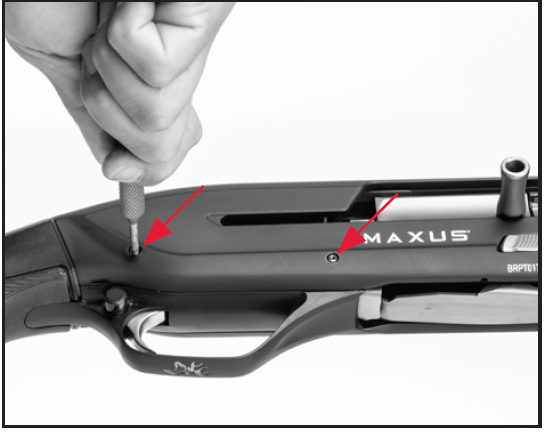
Push the trigger group pins through the receiver.
Figure 28
Figure 28
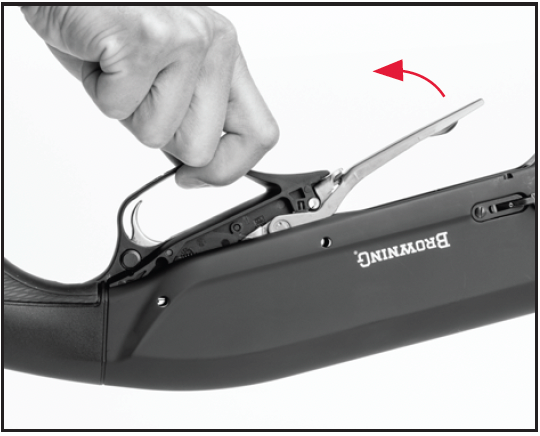
Lift the trigger group out of the receiver.
REMOVING THE TRIGGER GROUP
1. Place the bolt in the forward position by holding the bolt handle, depressing the bolt release button and slowly allowing the bolt assembly to move forward.
NEVER ALLOW THE ACTION TO SLAM CLOSED BY PRESSING THE BOLT RELEASE BUTTON WITHOUT THE BARREL INSTALLED. IF THE SLIDE ASSEMBLY IS RELEASED FORWARD WITH THE BARREL REMOVED, THE BOLT HANDLE WILL STRIKE THE RECEIVER AND CAUSE DAMAGE.
2. Use a punch or similar object to push inward on the trigger guard pins, taking care not to scratch the receiver (Figure 27). Trigger group pins may be removed from either side of the receiver. Push the trigger group pins through the receiver. Pull on them from the opposite side to remove them.
3. Grasp the trigger guard and pull it up and out of the receiver (Figure 28).
4. Perform any cleaning of the parts and receiver cavity as necessary. We suggest cleaning the trigger group with a quality aerosol gun solvent. Allow it to dry and then very lightly oil the moving parts.
DO NOT DISASSEMBLE THE TRIGGER GROUP BEYOND THIS POINT.
REINSTALLATION OF THE TRIGGER GROUP
1. Make sure the bolt is in the forward position.
2. Insert the trigger group into the receiver. Align the holes in the trigger group with the holes on each side of the receiver.
3. Insert the trigger group pins and gently tap them into place with a plastic or wooden mallet, using caution not to scratch the receiver.
SERVICING THE BOLT ASSEMBLY
BEFORE REMOVING THE BOLT ASSEMBLY, PLACE THE “SAFETY” IN THE ON SAFE POSITION. OPEN THE ACTION AND MAKE CERTAIN YOUR SHOTGUN IS COMPLETELY UNLOADED. KEEP THE MUZZLE POINTED IN A SAFE DIRECTION. FAILURE TO FOLLOW THESE WARNINGS COULD RESULT IN SERIOUS INJURY OR DEATH.
BEFORE REMOVING THE BOLT ASSEMBLY, PLACE THE “SAFETY” IN THE ON SAFE POSITION. OPEN THE ACTION AND MAKE CERTAIN YOUR SHOTGUN IS COMPLETELY UNLOADED. KEEP THE MUZZLE POINTED IN A SAFE DIRECTION. FAILURE TO FOLLOW THESE WARNINGS COULD RESULT IN SERIOUS INJURY OR DEATH.
WEAR EYE PROTECTION WHEN DISASSEMBLING AND CLEANING YOUR SHOTGUN TO PREVENT SPRINGS, SPRING-LOADED PARTS, SOLVENTS OR OTHER AGENTS FROM CONTACTING YOUR EYES, RESULTING IN INJURY.
WEAR EYE PROTECTION WHEN DISASSEMBLING AND CLEANING YOUR SHOTGUN TO PREVENT SPRINGS, SPRING-LOADED PARTS, SOLVENTS OR OTHER AGENTS FROM CONTACTING YOUR EYES, RESULTING IN INJURY.
KEEP ALL AMMUNITION AWAY FROM THE CLEANING AREA. NEVER TEST THE MECHANICAL FUNCTION OF YOUR SHOTGUN WITH LIVE AMMUNITION. FAILURE TO FOLLOW THESE WARNINGS COULD RESULT IN SERIOUS INJURY OR DEATH.
KEEP ALL AMMUNITION AWAY FROM THE CLEANING AREA. NEVER TEST THE MECHANICAL FUNCTION OF YOUR SHOTGUN WITH LIVE AMMUNITION. FAILURE TO FOLLOW THESE WARNINGS COULD RESULT IN SERIOUS INJURY OR DEATH.
Figure 29
Figure 29
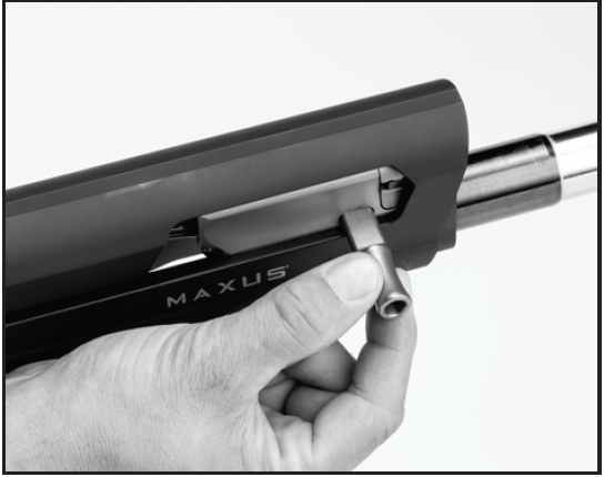
Pull outward to remove the bolt handle.
Figure 30
Figure 30
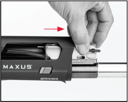
Slide the bolt forward and out of the receiver.
REMOVING THE BOLT ASSEMBLY
1. Remove the barrel, gas piston, piston sleeve and piston sleeve spring as explained previously.
2. Prior to removing the bolt assembly, it is preferred to first remove the trigger group, as explained previously.
3. Place the bolt in the forward position by holding the bolt handle, depressing the bolt release button and slowly allowing the bolt assembly to move forward.
NEVER ALLOW THE ACTION TO SLAM CLOSED BY PRESSING THE BOLT RELEASE BUTTON WITHOUT THE BARREL INSTALLED. IF THE SLIDE ASSEMBLY IS RELEASED FORWARD WITH THE BARREL REMOVED, THE BOLT HANDLE WILL STRIKE THE RECEIVER AND CAUSE DAMAGE.
4. Remove the bolt handle by pulling the bolt handle outward (Figure 29).
5. Press the bolt release button and slide the bolt assembly forward and out of the receiver (Figure 30).
6. The bolt and bolt slide can now be separated for cleaning (Figure 31). Perform cleaning of the bolt and receiver cavity as necessary
Figure 31
Figure 31
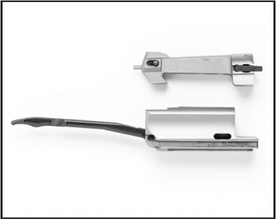
The bolt and bolt slide can be separated for cleaning.
Figure 32
Figure 32
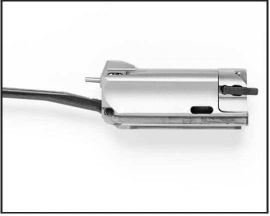
The bolt shown assembled.
DO NOT DISASSEMBLE THE BOLT ASSEMBLY BEYOND THIS POINT.
REINSTALLATION OF THE BOLT ASSEMBLY
1. Reassemble the bolt and bolt slide (Figure 32).
2. Place a few drops of oil in the grooves in the bolt to lubricate the bolt slide rails (Figure 3)
3. Align the rails on the bolt slide with the grooves in the receiver. Press the bolt release button and slide the bolt assembly into the receiver, bolt slide link end first.
4. Ensure the bolt slide link fits into the socket in the recoil spring follower (Figure 33).
5. Replace the bolt handle by inserting it in its slot in the bolt.
6. Open and close the action several times to make sure the bolt slide link and recoil spring follower are properly engaged.
Figure 33
Figure 33
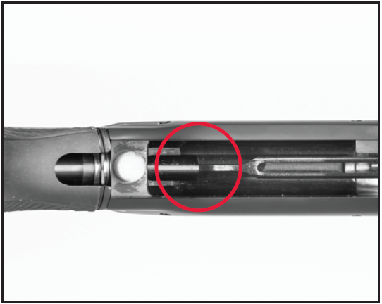
Guide the bolt slide link into its socket in the recoil spring follower.
NEVER ALLOW THE ACTION TO SLAM CLOSED BY PRESSING THE BOLT RELEASE BUTTON WITHOUT HAVING THE BARREL INSTALLED. DAMAGE WILL RESULT TO THE RECEIVER AND BOLT HANDLE.
CLEANING THE ACTION
1. When the action becomes excessively dirty, remove the trigger group and bolt assemblies from the receiver as explained under “Removing the Trigger Group” and “Removing the Bolt Assembly”. Clean with a gun solvent as necessary, using a nylon brush to loosen any caked-on grime. Wipe the receiver cavity clean. Lightly oil the cavity and wipe it dry. No further disassembly is required for cleaning.
2. Reassemble the trigger group, bolt assembly, gas system and the barrel to the receiver as explained previously. Then wipe all exposed metal surfaces with an oiled cloth, making sure to wipe clean all finger marks where moisture could accumulate.
3. The barrel and action should be inspected thoroughly to be certain no cleaning patches have been inadvertently left in them.
LUBRICATING THE ACTION TUBE AND SPRING
BEFORE LUBRICATING THE ACTION TUBE AND SPRING, PLACE THE “SAFETY” IN THE ON SAFE POSITION. OPEN THE ACTION AND MAKE CERTAIN YOUR SHOTGUN IS COMPLETELY UNLOADED. KEEP THE MUZZLE POINTED IN A SAFE DIRECTION. FAILURE TO FOLLOW THESE WARNINGS COULD RESULT IN SERIOUS INJURY OR DEATH.
BEFORE LUBRICATING THE ACTION TUBE AND SPRING, PLACE THE “SAFETY” IN THE ON SAFE POSITION. OPEN THE ACTION AND MAKE CERTAIN YOUR SHOTGUN IS COMPLETELY UNLOADED. KEEP THE MUZZLE POINTED IN A SAFE DIRECTION. FAILURE TO FOLLOW THESE WARNINGS COULD RESULT IN SERIOUS INJURY OR DEATH.
WEAR EYE PROTECTION WHEN DISASSEMBLING AND LUBRICATING YOUR SHOTGUN TO PREVENT SPRINGS, SPRING-LOADED PARTS, SOLVENTS OR OTHER AGENTS FROM CONTACTING YOUR EYES, RESULTING IN INJURY.
WEAR EYE PROTECTION WHEN DISASSEMBLING AND LUBRICATING YOUR SHOTGUN TO PREVENT SPRINGS, SPRING-LOADED PARTS, SOLVENTS OR OTHER AGENTS FROM CONTACTING YOUR EYES, RESULTING IN INJURY.
KEEP ALL AMMUNITION AWAY FROM THE CLEANING AREA. NEVER TEST THE MECHANICAL FUNCTION OF YOUR SHOTGUN WITH LIVE AMMUNITION. FAILURE TO FOLLOW THESE WARNINGS COULD RESULT IN SERIOUS INJURY OR DEATH.
KEEP ALL AMMUNITION AWAY FROM THE CLEANING AREA. NEVER TEST THE MECHANICAL FUNCTION OF YOUR SHOTGUN WITH LIVE AMMUNITION. FAILURE TO FOLLOW THESE WARNINGS COULD RESULT IN SERIOUS INJURY OR DEATH.
Figure 34
Figure 34
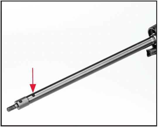
Place a few drops of oil in the opening in the action tube.
If you frequently use your shotgun in inclement weather conditions, oiling the action tube and spring will aid in maintaining the performance and reliability of your firearm.
1. Remove the recoil pad and buttstock as explained previously.
2. Place a few drops of high-quality lightweight gun oil in the opening in the rear of the action tube (Figure 34).
DO NOT ATTEMPT TO REMOVE THE ACTION SPRING FROM THE ACTION TUBE. THE ACTION TUBE IS EASILY DAMAGED AND THE ACTION SPRING IS UNDER SPRING TENSION. FAILURE TO FOLLOW THIS WARNING COULD RESULT IN SERIOUS INJURY OR DAMAGE YOUR SHOTGUN.
DO NOT ATTEMPT TO REMOVE THE ACTION SPRING FROM THE ACTION TUBE. THE ACTION TUBE IS EASILY DAMAGED AND THE ACTION SPRING IS UNDER SPRING TENSION. FAILURE TO FOLLOW THIS WARNING COULD RESULT IN SERIOUS INJURY OR DAMAGE YOUR SHOTGUN.
3. Hold the shotgun with the muzzle down. Rotate the shotgun and cycle the action using the bolt handle to operate the action several times to evenly disperse the oil on the spring and inside the action tube.
DO NOT USE EXCESSIVE LUBRICANT. USING TOO MUCH LUBRICANT CAN INTERFERE WITH THE FUNCTIONING OF YOUR SHOTGUN. DO NOT SPRAY SOLVENT INSIDE THE ACTION TUBE.
4. Carefully rest the shotgun vertically on a rag with the action tube down for 15 minutes to allow excess oil to drain out of the action tube. Wipe away any excess oil.
5. Lightly lubricate the external surface of the action tube.
6. Install the buttstock and recoil pad as explained previously.
NEVER ATTEMPT TO TAKE YOUR FIREARM APART FURTHER THAN EXPLAINED IN THIS OWNER’S MANUAL. YOUR FIREARM IS A SPECIALIZED, FINELY FITTED MECHANISM. YOU MAY PERMANENTLY DAMAGE IT BY ATTEMPTING TO DISASSEMBLE THE INNER MECHANISM ASSEMBLIES. IF FURTHER DISASSEMBLY FOR SERVICE OR CLEANING IS REQUIRED, TAKE YOUR FIREARM TO A QUALIFIED GUNSMITH, OR CONTACT OUR ARNOLD, MISSOURI SERVICE FACILITY AS EXPLAINED UNDER “SERVICE OR REPAIR”.
MAINTENANCE OF OIL FINISH STOCKS
Keeping the oil-finished wood surface on your firearm looking its
best requires only a small amount of maintenance. When the surface becomes spotted or dull, the affected area(s) can be treated using rubbing alcohol on a soft, lint free cloth and allowed to dry. A small amount of a linseed oil-based finish, such as Watco® Danish Oil Finish, Deft® Danish Oil Finish, or Formby’s® Tung Oil Finish should then be applied to the surface of the wood with a soft, lint free cloth according to the manufacturer’s instructions. To treat the checkering, a small amount of oil-based finish can be applied and then distributed evenly using a toothbrush or other soft bristled brush.
MODELS WITH SPECIAL FINISHES
As with any firearm, the only way to preserve its pristine condition and collector appeal is to never handle or fire it, which in turn would deprive you of much of the enjoyment that comes with owning a fine Browning firearm.
While special finishes such as engraving and gold plating greatly enhance the aesthetic appeal of your shotgun, please be aware that
they are no more durable, and in some cases may even be slightly less durable than more common firearm finishes.
As you use your shotgun, you can expect special finishes to wear in much the same manner as any other firearm finish. These marks are the honest product of the hours spent enjoying your firearm and each scuff and scratch will probably have a good story to go along with it.
SERVICE OR REPAIR
If your firearm should require service or repairs, we suggest you first contact a local recommended Browning Firearms Service Center. To locate a service center visit browning.com, contact our Customer Service Department or your Browning firearms dealer for the address of the Service Center nearest you. Otherwise, you may send your firearm directly to our Service Department in Arnold, Missouri.
Parts listings, Firearm Service Center lists, service procedures, service/repair form and general product information are also found on the internet at browning.com. For technical questions about your firearm or service, contact:
United States customers contact:
Browning Firearm Status and
Technical Service
3005 Arnold Tenbrook Rd
Arnold, MO 63010-9406
Phone: (800) 322-4626
Canadian customers contact:
Browning Canada Sports Ltd/Ltée
5583 Chemin St-François
St-Laurent, Quebec H4S 1W6
Phone: (514) 333-7261
When returning your firearm for servicing, you must do the following:
1. Be sure it is completely unloaded.
2. Remove any optics, optic mounts or other accessories.
3. Package it securely in a cardboard container.
4. Enclose the service/repair form available at browning.com or a letter that clearly describes the trouble experienced, the ammunition used and the repairs desired. Also include your name, e-mail address (if possible) and a daytime phone number where you can be reached.
5. Never return ammunition with your firearm. It is against postal and most commerce regulations.
STATE-BY-STATE WARNINGS
CERTAIN STATES REQUIRE, BY LAW, THAT THEIR OWN SPECIFIED WARNING NOTICES BE INCLUDED BY THE MANUFACTURER, DISTRIBUTOR, OR RETAIL DEALER WITH FIREARMS SOLD IN THAT STATE. BROWNING SELLS ITS PRODUCTS IN COMPLIANCE WITH APPLICABLE LAWS AND REGULATIONS. BECAUSE OUR PRODUCTS MAY BE SOLD IN THESE STATES, WE INCLUDE THE FOLLOWING:
CALIFORNIA

Firearms must be handled responsibly and securely stored to prevent access by children and other unauthorized users. California has strict laws pertaining to firearms, and you may be fined or imprisoned if you fail to comply with them. Visit the Web site of the California Attorney General at https://oag.ca.gov/firearms for information on firearm laws applicable to you and how you can comply.
Prevent child access by always keeping guns locked away and unloaded when not in use. If you keep a loaded firearm where a child obtains and improperly uses it, you may be fined or sent to prison.
If you or someone you know is contemplating suicide, please call the National Suicide Prevention Lifeline at 1-800-273-TALK (8255).

Las armas de fuego deben de ser manipuladas responsablemente y almacenadas en sitios seguros para prevenir el acceso a ellas por parte de niños y personas sin autorización. California cuenta con leyes estrictas sobre las armas de fuego, y puede ser multado y encarcelado si no las obedece. Visite la página web de California Attorney General, https://oag.ca.gov/firearms para más información sobre cómo cumplir con las leyes de armas de fuego.
Prevenga el acceso de los niños a las armas de fuego manteniéndolas siempre en un lugar seguro, bajo llave y descargadas cuando no estén en uso. Si usted deja un arma cargada al alcance de un niño, y éste la utiliza indebidamente,usted podría ser multado e incluso enviado a la cárcel.
Si usted o alguien que conoce está pensando en suicidarse, llame a la línea Nacional de Prevención del Suicidio al 1-800-273-TALK (8255)
CONNECTICUT
“UNLAWFUL STORAGE OF A LOADED FIREARM MAY RESULT IN IMPRISONMENT OR FINE.”
FLORIDA
“IT IS UNLAWFUL, AND PUNISHABLE BY IMPRISONMENT AND FINE, FOR ANY ADULT TO STORE OR LEAVE A FIREARM IN ANY PLACE WITHIN THE REACH OR EASY ACCESS OF A MINOR UNDER 18 YEARS OF AGE OR TO KNOWINGLY SELL OR OTHERWISE TRANSFER OWNERSHIP OR POSSESSION OF A FIREARM TO A MINOR OR A PERSON OF UNSOUND MIND.”
MAINE
“ENDANGERING THE WELFARE OF A CHILD IS A CRIME. IF YOU LEAVE A FIREARM AND AMMUNITION WITHIN EASY ACCESS OF A CHILD, YOU MAY BE SUBJECT TO FINE, IMPRISONMENT OR BOTH. KEEP FIREARMS AND AMMUNITION SEPARATE. KEEP FIREARMS AND AMMUNITION LOCKED UP. USE TRIGGER LOCKS.”
MARYLAND
“WARNING: Children can operate firearms which may cause death or serious injury. It is a crime to store or leave a loaded firearm in any location where an individual knew or should have known that an unsupervised minor would gain access to the firearm. Store your firearm responsibly!”
MASSACHUSETTS
“WARNING FROM THE MASSACHUSETTS ATTORNEY GENERAL: This handgun is not equipped with a device that fully blocks use by unauthorized users. More than 200,000 firearms like this one are stolen from their owners every year in the United States. In addition, there are more than a thousand suicides each year by younger children and teenagers who get access to firearms. Hundreds more die from accidental discharge. It is likely that many more children sustain serious wounds, or inflict such wounds accidentally on others. In order to limit the chance of such misuse, it is imperative that you keep this weapon locked in a secure place and take other steps necessary to limit the possibility of theft or accident. Failure to take reasonable preventative steps may result in innocent lives being lost, and in some circumstances may result in your liability for these deaths.”
“IT IS UNLAWFUL TO STORE OR KEEP A FIREARM, RIFLE, SHOTGUN OR MACHINE GUN IN ANY PLACE UNLESS
THAT WEAPON IS EQUIPPED WITH A TAMPER RESISTANT SAFETY DEVICE OR IS STORED OR KEPT IN A SECURELY LOCKED CONTAINER.”
NEW JERSEY
“IT IS A CRIMINAL OFFENSE TO LEAVE A LOADED FIREARM WITHIN EASY ACCESS OF A MINOR.”
NEW YORK CITY, NEW YORK
“THE USE OF A LOCKING DEVICE OR SAFETY LOCK IS ONLY ONE ASPECT OF RESPONSIBLE WEAPON STORAGE. ALL WEAPONS SHOULD BE STORED UNLOADED AND LOCKED IN A LOCATION THAT IS BOTH SEPARATE FROM THEIR AMMUNITION AND INACCESSIBLE TO CHILDREN AND ANY OTHER UNAUTHORIZED PERSONS. NEW YORK CITY LAW PROHIBITS, WITH CERTAIN EXCEPTIONS, ANY PERSON FROM ACQUIRING MORE THAN ONE FIREARM, OR MORE THAN ONE RIFLE OR SHOTGUN, WITHIN A 90-DAY PERIOD.”
NORTH CAROLINA
“IT IS UNLAWFUL TO STORE OR LEAVE A FIREARM THAT CAN BE DISCHARGED IN A MANNER THAT A REASONABLE PERSON SHOULD KNOW IS ACCESSIBLE TO A MINOR.”
Any person who resides in the same premises as a minor, owns or possesses a firearm, and stores or leaves the firearm (i) in a condition that the firearm can be discharged and (ii) in a manner that the person knew or should have known that an unsupervised minor would be able to gain access to the firearm, is guilty of a Class 1 misdemeanor if a minor gains access to the firearm without the lawful permission of the minor’s parents or a person having charge of the minor and the minor:
(1) Possesses it in violation of G.S. 14-269.2(b)
(2) Exhibits it in a public place in a careless, angry, or threatening manner;
(3) Causes personal injury or death with it not in
self defense; or
(4) Uses it in the commission of a crime.
TEXAS
“IT IS UNLAWFUL TO STORE, TRANSPORT, OR ABANDON AN UNSECURED FIREARM IN A PLACE WHERE CHILDREN ARE LIKELY TO BE AND CAN OBTAIN ACCESS TO THE FIREARM.”
WISCONSIN
“IF YOU LEAVE A LOADED FIREARM WITHIN THE REACH OR EASY ACCESS OF A CHILD YOU MAY BE FINED OR IMPRISONED OR BOTH IF THE CHILD IMPROPERLY DISCHARGES, POSSESSES, OR EXHIBITS THE FIREARM.”
PLEASE CONSULT YOUR LOCAL FEDERALLY LICENSED FIREARMS
RETAILER, STATE POLICE OR LOCAL POLICE FOR ADDITIONAL WARNINGS THAT MAY BE REQUIRED BY LOCAL LAW OR REGULATION. FIREARMS REGULATIONS CHANGE CONSTANTLY AND YOUR LOCAL AUTHORITIES ARE THE BEST SOURCE FOR THE MOST CURRENT INFORMATION ON SUCH LEGAL MATTERS.
US: Morgan, Utah 84050-9326
CANADA: Browning Canada Sports Ltd/Ltée, St-Laurent, Quebec H4S 1W6
INTL: Parc Industriel des Hauts-Sarts, B-4040 Herstal, Belgium