

Operation and care of
2000 Automatic Gas Operated Shotgun
2000 Automatic Gas Operated Shotgun
We are proud that you have chosen a Browning. In its manufacture we have endeavored to incorporate the very finest in materials and craftsmanship, and with just reasonable care this gun should provide you with many years of pleasure and dependable service. If, by any chance, you have any observations to make regarding its performance or appearance, we hope you will write us immediately. We would also like to know more about you as a Browning owner and would be grateful if you could take but a moment to complete and return the marketing survey card found on the inside back cover.
Thank you. Browning.
These instructions should be carefully noted.
NOMENCLATURE
NOMENCLATURE
In conventional gun terminology, the position and movement of gun parts are described as they occur with the gun horizontal, in normal firing position; i.e., the muzzle is forward or front; butt stock is rearward or rear; trigger is underneath; the rib is on top.
CAUTION
CAUTION
A. ALWAYS VISUALLY CHECK YOUR SHOTGUN - to be certain that it does not inadvertently contain any ammunition. Whenever you pick up a gun, immediately make sure the gun is on safe and the chamber and magazine are unloaded.
B. ALWAYS KEEP YOUR GUN’S SAFETY IN THE “ON SAFE” POSITION - even if you are certain the gun is unloaded. Check and double check, frequently while you are hunting. Be sure contact with a twig, a tumble on slippery terrain, the moment of excitement after a shot, or a dozen other seemingly innocent incidents have not left you with a gun, “off safe.”
Never point a gun you are certain is “on safe” at anything you do not intend to shoot. Safe gun handling does not stop with your gun’s mechanical safety. It starts there. Handle your gun at all times with deep respect and with alert consideration to all within its range.
C. ALWAYS KEEP THE MUZZLE OF YOUR GUN POINTED IN A SAFE DIRECTION - even though you are certain the gun is unloaded and “on safe.” Never point your gun at anything you do not intend to shoot.
D. ALWAYS UNLOAD YOUR SHOTGUN WHEN NOT IN USE - As a safety precaution it is preferable to disassemble your gun for storage. Store your gun and ammunition separately - beyond the reach of children.
E. DO NOT PUT A 20 GAUGE SHELL IN A 12 GAUGE GUN - if you value your gun and yourself. We strongly recommend that all shells of different gauges be stored in completely separate and well-marked containers. NEVER store shells of mixed gauges in a common container or IN YOUR POCKETS. EXAMINE EVERY SHELL YOU PUT IN YOUR GUN. The most certain way to bulge or rupture the finest barrel is to drop a 20 gauge shell into a 12 gauge chamber. The 20 gauge shell, unfortunately, will not fall completely through the barrel; its rim is caught by the FRONT of a 12 gauge chamber. Your gun will misfire, and under conditions of carelessness made lethal by haste, a 12 gauge shell can be loaded behind the 20. You could not deliberately have created a more serious hazard to your gun and yourself.
F. BEWARE OF BARREL OBSTRUCTIONS - for the safety of both your gun and yourself. Mud, snow and an infinite variety of other objects may inadvertently lodge in a barrel bore. It takes only one small obstruction to ruin (swell or rupture) the finest of shotgun barrels.
G. DO NOT SNAP THE HAMMER ON AN EMPTY CHAMBER - THE CHAMBER MAY NOT BE EMPTY! Treat every gun with the respect due a loaded gun - even though you are certain the gun is unloaded. It is unnecessary to snap the hammer to prevent weakening of the main spring. It will not weaken even though the hammer is left cocked indefinitely. Neither will snapping the hammer on an empty chamber damage or break the firing pin.
AMMUNITION: The gauge and maximum acceptable load are stamped on the right side of the barrel. Never use a load that exceeds these specifications. Magnum shells may be used so long as the cartridge length does not exceed the length stamped on the barrel. That is, a 12 gauge shotgun stamped “12 gauge shells - 2 3/4 inches” may use 2 3/4 inch 12 gauge Magnum loads but not 3 inch 12 gauge Magnum loads.
CAUTION: Do not take the measurement of an unfired shell to determine the length. An unfired 2 3/4" shell, for example, only measures about 2 1/2". Most shell boxes are stamped as to the length of the shells they contain and some shells are actually individually marked as to their length. The Browning 2000 must be used only with the gauge of ammunition stamped on the barrel. The barrel and action of this shotgun have been made with large safety margins over the pressures developed by established commercial loads. Nevertheless, Browning can assume no responsibility for incidents which occur through the use of cartridges of non-standard dimension or those developing excessive pressures.
GENERAL OPERATION
GENERAL OPERATION
This shotgun is gas-operated. A portion of the expanding powder gases is bled off through gas ports in the barrel and used to operate the mechanism. During rearward travel, the bolt extracts and ejects the spent shell and cocks the hammer. During forward travel, a new round is fed from the magazine to the chamber. This operation is semi-automatic; the trigger must be released and pulled to fire each successive shot. After the last shell has been fired, the breech bolt locks open. This of course, facilitates speedy reloading.
MOUNTING THE BARREL TO ACTION
MOUNTING THE BARREL TO ACTION
Your Browning 2000 is packaged and shipped with the forearm attached to the receiver and magazine tube. In order to install the barrel it is necessary to remove the forearm from the magazine tube and affix the forearm on the barrel before mounting the barrel to the action. Follow the steps below:
1. THOROUGHLY CLEAN ALL ANTI-RUST COMPOUND FROM THE BARREL, THE BORE AND OTHER METAL SURFACES. Remove with any good quality gun oil or gun cleaning solvent.
2. Unscrew the forearm cap and remove the forearm from the magazine tube.

3. Affix the forearm to the barrel by locating the entire forearm rearward of the barrel ring and gently sliding the forearm forward until the barrel ring is seated against the rubber forearm bushing (Figure 1). Do not force the rearward end of the forearm upward around the barrel as this could split the forearm.
4. Draw the breech bolt rearward so that it remains locked back. Be sure the safety is “on safe”.
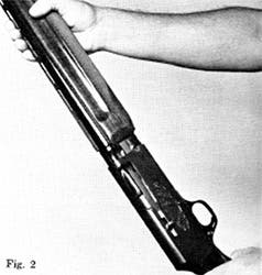
5. Grasp the butt stock by the pistol grip and anchor the butt end on your hip. With your other hand grasp the forearm and barrel and after a final glance through the bore to be sure there is no barrel obstruction, carefully work the forearm down the magazine tube and introduce the barrel extension into the receiver (Figure 2).
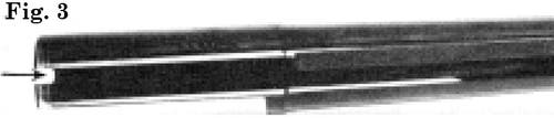
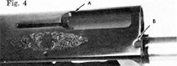
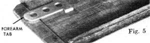
6. As the barrel and forearm are seated into final position, be certain the U-shaped cut in the barrel extension (Figure 3) mates fully against the barrel guide in the upper inside of the receiver (Point A, Figure 4). Also check that the metal forearm tabs in the rearward end of the forearm (Figure 5) slide into the opposing receiver recesses (Point B, Figure 4).
7. Screw the forearm cap onto the magazine tube. HAND TIGHTEN ONLY. Never apply a wrench or any kind of severe force.
Removing the barrel is simply done by reversing the above procedure. If you prefer to store your gun with the action and barrel separated, it is suggested that the forearm be attached to the magazine tube and receiver. This secures your forearm and prevents it from possible damage.
CLOSING THE BREECH
CLOSING THE BREECH
Do not press the carrier latch and let the breech bolt ride home under its own force, unless the bolt is actually feeding a round into the chamber. It is always advisable, whenever the bolt is being closed on an empty chamber or being closed after the barrel has been removed from the action, to hook your thumb or finger around the bolt operating handle and let the bolt ease forward.
CAUTION
CAUTION
At all times keep your hand and fingers away from the ejection port (breech bolt port) to avoid being struck by the breech bolt as it closes.
CROSS BOLT SAFETY
CROSS BOLT SAFETY
The cross bolt safety blocks the trigger from operating. In the “off safe” or “fire” position a red warning band is visible, on the left side of the trigger guard, alerting the shooter of the gun’s ready-to-fire status.
To accommodate left hand shooters, this safety can be reversed by a gunsmith in a matter of minutes. When reversed, of course, the red warning band will then appear on the right side of the trigger guard. Unlike many other guns with cross bolt safeties, no extra parts are necessary for this conversion.
LOADING
LOADING
BE SURE THE MUZZLE IS POINTED IN A SAFE DIRECTION, AND THE SAFETY IS “ON SAFE.”
The Browning 2000 is equipped with the speed loading system Browning Automatic shotguns are famous for. It is not necessary to jiggle the first round into the chamber and then trip the carrier latch (bolt release) to ready the first round for firing. Nor is it necessary to insert a round into the magazine and then cycle the bolt to chamber the first round.
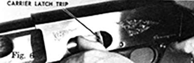
After being sure the breech bolt is locked open, all you do is thumb the first round into the loading port on the left side of the receiver. Push this first round forward so that the brass head of the shell is about an inch forward of the carrier latch trip (Figure 6.)
Release the shell by withdrawing your thumb completely out of the loading port and letting the shell slam rearward against the carrier latch trip. Instantly this round will be whisked into the chamber ready for firing!
(Remember to keep your fingers away from the ejection port on the opposite side of the receiver. The bolt drives forward with force during the loading of this first round.)
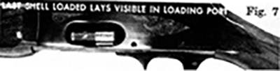
The second, third and fourth shells to be loaded are then thumbed completely into the magazine. You will not be able to insert the fifth shell you load completely into the magazine. This fifth shell (the second shell in line-up for firing) is inserted so that it lays in the loading port with the crimped end protruding only partly into the magazine (Figure 7).
Be certain that this shell lays straight and is entirely within the loading port. It is held firmly in this position and will not fall out or rattle.
This is also true when the plug is installed - the third (last) shell to be loaded (second in firing sequence) lays visible in the loading port.
SWITCH LOADS FAST
SWITCH LOADS FAST
The shell which lays visible in the loading port can be quickly removed, if you want to switch loads in a hurry. Suppose your 2000 is loaded with duck loads and geese decide to veer your way. Simply pluck the visible shell from the loading port and insert a goose load. Cycle the bolt. Your chambered duck load will eject, and the goose load will be chambered.
FIRING
FIRING
Once loaded, all that is necessary to fire the gun, of course, is to push the safety to the “fire” position and pull the trigger. The first shell will fire and be ejected. The second will automatically be chambered. The trigger must be released and pulled to fire each successive shot.
THE BREECH REMAINS OPEN after the last shot has been fired. This allows you to reload quickly, if you desire to.
BREAKING IN WITH LIGHT LOADS
BREAKING IN WITH LIGHT LOADS
If the initial shooting of your 12 ga B-2000 is done with trap, skeet or light field loads, you may experience a few malfunctions in the first box or two of shells. After this short break-in period your B-2000 will operate well with light or heavy loads.
UNLOADING
UNLOADING
As well as speed loading, the Browning 2000 features speed unloading. Before unloading, BE SURE THE SAFETY IS “ON SAFE” AND THE MUZZLE IS POINTED IN A SAFE DIRECTION.
The shells in the loading port and magazine are unloaded first. Simply ease the shell in the loading port outward with your thumb until you can remove it. To remove the shells in the magazine depress the cartridge stop. The cartridge stop (Figure 8) projects from the bottom of the bolt slide.
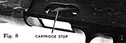
With the cartridge stop depressed let each shell ride rearward and out of the loading port. In this manner you can remove all the shells except the one in the chamber. This shell is removed by drawing the breech bolt rearward and catching the shell as it ejects.
MAGAZINE PLUG
MAGAZINE PLUG
A magazine plug, restricting the Browning 2000’s capacity to 3 shots, is furnished with each gun.
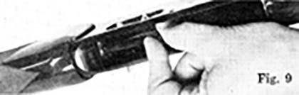
TO INSTALL THE PLUG first remove the trigger group (see pages 23 and 24). Merely push the solid end of the magazine plug through the opening in the follower until the plug is completely within the magazine (Figure 9). Important: Be certain that the split end of the magazine plug is rearward.
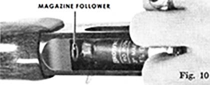
TO REMOVE THE PLUG first remove the trigger group (see pages 23 and 24). Then take an empty shotshell and place the mouth of the shell against the magazine follower (Figure 10).
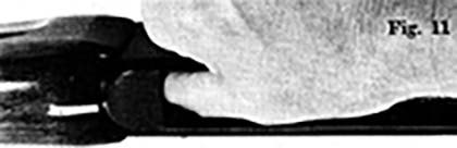
Thumb this empty shell far enough into the magazine to place a second empty shell behind the first. Then press the second empty shell into the magazine (Figure 11). Some pressure with the thumb will be required, since it causes the split rearward end of the magazine plug to compress and emerge through the hole in the magazine follower and into the inside of the first empty shell. Ease the shells rearward and out of the magazine.
You will now see the plug protruding from the follower. Simply pull the plug from the magazine follower (Figure 9). Now reinstall the trigger group.
CAPACITY
CAPACITY
With the plug removed your 2000 has a capacity of five 2 3/4" shells. When it is set up to fire 3" magnum shells with a 3" magnum barrel, the capacity is four 3" shells.
With the plug installed the capacity is reduced to three shells - whether the 2000 is set up to fire 2 3/4" shells only or 3” magnum shells.
INTERNAL GAS SYSTEM
INTERNAL GAS SYSTEM
The Browning 2000 has a uniquely designed, extremely reliable gas system. It is compactly contained within the magazine tube. This makes it less accessible to dirt and allows a slim forearm design.
The gas is sealed off so that it cannot blow rearward into the forearm, along the action bar assembly and toward the action The gas is vented forward through the hole in the forearm cap.
How often should you strip down the gas system and clean it? There is no rule of thumb. It depends somewhat on the type of ammunition you use and how heavily you shoot your gun. Hunters will probably want to clean the system at the season’s end. Trap and skeet shooters will perhaps want to clean it more frequently It’s a matter of shooting conditions and judgment.
DISMANTLING AND CLEANING THE GAS SYSTEM
DISMANTLING AND CLEANING THE GAS SYSTEM
Dismantling the gas system is very simple. Make sure the safety is on and draw the breech bolt rearward until it locks open. Unscrew the forearm cap and remove the barrel and forearm.
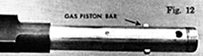
You will notice the gas piston bar projecting from each side of the magazine tube (Figure 12).
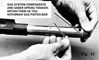
Remove this simply by pushing it from one side and withdrawing it from the other (Figure 13).
As you do this hold your finger or thumb against the gas cylinder plug which protrudes slightly from the forward end of the magazine tube (Figure 13).
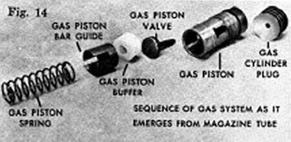
This is necessary because the gas system is under spring tension. Now ease the gas system components forward out of the magazine tube. Carefully note the sequence of parts as you withdraw them from the magazine tube (Figure 14).
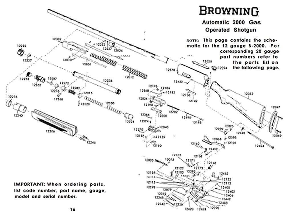
PARTS LIST
PARTS LIST
12 AND 20 GAUGE GAS OPERATED SHOTGUN B-2000
12 AND 20 GAUGE GAS OPERATED SHOTGUN B-2000
| PART # | DESCRIPTION |
| 12001 | Action Bar Left 12, 20 ga. |
| 12005 | Action Bar Right 12, 20 ga. |
| 12010 | Action Bar Right (4), 12, 20 ga. |
| 12012 | Action Spring 12 ga. |
| 12014 | Action Spring 20 ga. |
| *12024 | Barrel Ring 12 ga. |
| 12025 | Barrel Ring 20 ga. |
| *12028 | Barrel Guide 12, 20 ga. |
| *12034 | Bolt 12 ga. |
| *12036 | Bolt 20 ga. |
| 12040 | Bolt Slide 12 ga. |
| 12042 | Bolt Slide 20 ga. |
| 12046 | Butt Plate 20 ga. |
| 12047 | Butt Plate 12 ga. |
| 12049 | Butt Plate Screw 12, 20ga. |
| 12052 | Butt Stock, Field 12 ga. |
| 12054 | Butt Stock, Trap 12 ga. |
| 12056 | Butt Stock, Skeet 12 ga. |
| 12058 | Butt Stock, Field 20 ga. |
| 12060 | Butt Stock, Skeet 20 ga. |
| *12068 | Carrier 12 ga. |
| *12070 | Carrier 20 ga. |
| 12075 | Carrier Cartridge Limit Pin12, 20 ga. |
| 12079 | Carrier Cartridge Pin 12 ga. |
| 12080 | Carrier Cartridge Pin 20 ga. |
| 12081 | Carrier Cartridge Spring 12, 20 ga. |
| 12085 | Carrier Cartridge Stop 12 ga. |
| 12087 | Carrier Cartridge Stop |
| 12090 | Carrier Dog 12 ga. |
| 12092 | Carrier Dog 20 ga. |
| 12095 | Carrier Dog Pin 12, 20 ga. |
| 12098 | Carrier Dog Spring 12, 20 ga. |
| 12101 | Carrier Dog Spring Guide 12, 20 ga. |
| 12105 | Carrier Latch 12 ga. |
| Carrier Latch 20 ga. | |
| 12113 | Carrier Latch Pin 12 ga. |
| Carrier Latch Pin.20 ga. | |
| 12115 | Carrier Latch Spring 12, 20 ga. |
| 12118 | Carrier Latch Spring Plunger 12, 20 ga. |
| 12122 | Carrier Latch Trip 12 ga. |
| 12124 | Carrier Latch Trip 20 ga. |
| 12128 | Carrier Latch Trip Pin 12 ga. |
| 12130 | Carrier Latch Trip Pin 20 ga. |
| 12132 | Carrier Pin 12, 20 ga. |
| 12136 | Carrier Release 12 ga. |
| 12138 | Carrier Release 20 ga. |
| 12142 | Carrier Release Pin 12, 20 ga. |
| 12146 | Carrier Spring 12, 20 ga. |
| 12150 | Cartridge Stop 12, 20 ga. |
| 12156 | Cartridge Stop 12, 20 ga. |
| 12159 | Cartridge Stop Spring 12, 20 ga. |
| *12162 | Disconnector 12, 20 ga. |
| 12168 | Disconnector Pin 12, 20 ga. |
| 12171 | Disconnector Spring 12, 20 ga. |
| 12173 | Disconnector Spring Plunger 12, 20 ga. |
| 12176 | Extractor 12, 20 ga. |
| Extractor Spring 12, 20 ga. | |
| 12186 | Extractor Spring Plunger 12, 20 ga. |
| 12190 | Firing Pin 12, 20 ga. |
| 12198 | Firing Pin Bushing Pin 12, 20 ga. |
| 12202 | Firing Pin Spring 12, 20 ga. |
| 12206 | Forearm, Field 12 ga. |
| 12208 | Forearm, Semi Beavertail 12 ga. |
| 12212 | Forearm, Field 20 ga. |
| 12214 | Forearm, Semi Beavertail 20 ga. |
| 12216 | Forearm Bushing 12 ga. |
| Forearm Bushing 20 ga. | |
| 12220 | Forearm Bushing Washer 20 ga. only |
| 12222 | Forearm Cap 12 ga. |
| 12223 | Forearm Cap w/Eyelet 12 ga. |
| 12224 | Forearm Cap 20 ga. |
| 12225 | Forearm Cap w/Eyelet 20 ga. |
| 12227 | Forearm Cap Buffer 12 ga. |
| 12229 | Forearm Cap Buffer 20 ga. |
| 12231 | Forearm Cap Buffer Washer 20 ga. only |
| 12232 | Forearm Cap Plunger 12, 20 ga. |
| PART # | DESCRIPTION |
| 12237 | Forearm Cap PlungerSpring 12, 20 ga. |
| *12240 | Forearm Liner 12 ga. |
| *12242 | Forearm Liner 20 ga. |
| *12246 | Forearm Tabs 12 ga. |
| *12248 | Forearm Tabs 20 ga. |
| 12252 | Gas Cylinder Plug 12 ga. |
| 12254 | Gas Cylinder Plug 20 ga. |
| 12262 | Gas Piston 12 ga. |
| 12264 | Gas Piston 20 ga. |
| 12268 | Gas Piston Bar 12 ga. |
| 12270 | Gas Piston Bar 20 ga. |
| 12272 | Gas Piston Bar Guide 12 ga. |
| 12274 | Gas Piston Bar Guide 20 ga. |
| 12276 | Gas Piston Buffer 12 ga. |
| 12278 | Gas Piston Buffer 20 ga. |
| 12282 | Gas Piston Spring 12 ga. |
| 12284 | Gas Piston Spring 20 ga. |
| 12287 | Gas Piston Valve 12 ga. |
| 12289 | Gas Piston Valve 20 ga. |
| *12292 | Hammer 12 ga. |
| *12294 | Hammer 20 ga. |
| 12298 | Hammer Pin 12 ga. |
| 12299 | Hammer Pin 20 ga. |
| 12302 | Inertia Piece 12 ga. |
| 12304 | Inertia Piece 20 ga. |
| 12308 | Locking Block 12 ga. |
| 12310 | Locking Block 20 ga. |
| 12312 | Magazine Adaptor Three Shot 12, 20 ga. |
| 12315 | Magazine Base 12 ga. |
| 12318 | Magazine Base 20 ga. |
| 12320 | Magazine Base Pin 12 ga. |
| 12322 | Magazine Base Pin 20 ga. |
| 12324 | Magazine Follower 12 ga. |
| 12326 | Magazine Follower 20 ga. |
| 12330 | Magazine Spring 12 ga. |
| 12332 | Magazine Spring 20 ga. |
| *12336 | Magazine Tube 12 ga. |
| *12338 | Magazine Tube 20 ga. |
| 12342 | Mainspring-Right or Left 12, 20 ga. |
| 12348 | Mainspring Guide-Right or Left 12, 20 ga. |
| 12352 | Mainspring Pin-Hammer 12 ga. |
| 12354 | Mainspring Pin-Hammer 20 ga. |
| 12356 | Mainspring Pin-Trigger Guard 12 ga. |
| 12358 | Mainspring Pin-Trigger Guard 20 ga. |
| 12360 | Operating Handle 12 ga. |
| 12362 | Operating Handle 20 ga. |
| 12366 | Operating Handle Retainer Pin 12, 20 ga. |
| 12370 | Operating Handle Retainer Pin 12, 20 ga. |
| 12374 | Operating Handle Retainer Spring 12, 20 ga. |
| *12378 | Receiver Assembly 12 ga. |
| †*12379 | Receiver 12 ga. Field Type 2 |
| †*12380 | Receiver Assembly 12 ga.Trap & Skeet |
| *12384 | Receiver Assembly 20 ga. |
| †*12385 | Receiver 20 ga. Field Type 2 |
| †*12386 | Receiver Assembly 20 ga. |
| 12394 | Receiver Buffer 12 ga. |
| 12396 | Receiver Buffer 20 ga. |
| 12398 | Safety Crossbolt 12, 20 ga. |
| 12402 | Safety Spring 12, 20 ga. |
| 12406 | Safety Spring Plunger 12, 20 ga. |
| 12408 | Safety Spring Retaining Pin 12, 20 ga. |
| *12415 | Sear 12 ga. |
| *12417 | Sear 20 ga. |
| 12420 | Sear Pin 12, 20 ga. |
| 12421 | Sight Base Front 12, 20 ga. |
| 12422 | Sight Bead Front 12, 20 ga. |
| 12424 | Stock Bolt 12, 20 ga. |
| 12428 | Stock Bolt Washer 12, 20 ga. |
| *12432 | Trigger 12 ga. |
| *12434 | Trigger 20 ga. |
| 12438 | Trigger Pin 12, 20 ga. |
| 12442 | Trigger Guard 12 ga. |
| 12445 | Trigger Guard 20 ga. |
| 12452 | Trigger Guard Retaining Pin 12 ga. |
| 12453 | Trigger Guard Retaining Pin 20 ga. |
| 12454 | Trigger Guard Retaining Pin Bushing 12, 20 ga. |
| 12458 | Trigger Guard Retaining Pin Spring 12, 20 ga. |
| 12462 | Trigger Guard Shield 12 ga. |
| 12464 | Trigger Guard Shield 20 ga. |
May be purchased only by holder of valid Federal Firearms license.
*Indicates part must be fitted by our Service Department or Qualified Gunsmith.
† In 1977 production, these two parts were combined to form one integral part.
CAUTION: Do not trip the carrier latch and let the bolt fly home when the gas piston bar is removed. The operating handle of the bolt will slam into the front of the receiver and damage it. If you wish to close the bolt at this time, make sure you hold onto the operating handle and let the bolt very slowly ride forward until the operating handle rests against the forward edge of the ejection port.
You are now ready to wipe out the magazine tube and clean the components. The gas piston and gas cylinder plug are bronze. If you decide to scrub these components with a brush, be sure you use a typical brass bore cleaning type brush and not a steel brush or any other type that will scratch these components.
Use a good quality powder solvent, such as Browning Liquid Gunsmith, to clean the gas system components. Do not use gun oil. This will collect foreign matter. Keep these components clean and dry.
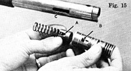
Reassemble the gas system components in the exact order as you removed them. Pay particular attention to lining up the slot in the gas piston bar guide (A, Figure 15) with the holes in the gas piston (B, Figure 15) and the magazine tube (C, Figure 15) so that you can easily insert the gas piston bar.
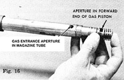
Be certain that the slot in the gas piston bar guide (A, Figure 15) is rearward. This is critical for proper functioning. Also be certain that the aperture in the forward end of the gas piston is located upward and in alignment with the gas entrance aperture in the top of the magazine tube (Figure 16).
To insure that you install the gas piston with this aperture upward, the slot C in the magazine tube and the slots A & B in the gas piston and gas piston bar guide are machined off center If after installing the gas system in the magazine tube, you cannot easily install the gas piston bar, you have not assembled the components properly. Remove them and be certain the aperture is located upward. Never under any circumstances tap the gas piston bar with a hammer or other object. If you cannot insert the bar with your fingers, you are not assembling the gas system correctly
Also during assembly be sure the concave surface of the gas cylinder plug bears against the gas piston.
(Of Interest: During disassembly of the gas system you will have noticed the white gas piston buffer. Buffers are also located in the forearm cap and in the rearward portion of the receiver. These act as shock absorbers greatly cushioning the forceful operation of the gas system and the energy it imparts to the bolt. They help to soften recoil, making your 2000 very pleasant to shoot.)
TO SHOOT 3" MAGNUMS
TO SHOOT 3" MAGNUMS
If the barrel of your Browning 2000 is chambered for 2 3/4" shells, all you need to shoot 3” magnum loads is an extra barrel chambered for 3” shells. You do not need to purchase a different action nor alter the gas system in any way. The gas ports in the barrels differ, so that you can interchange 2 3/4" chambered barrels and 3" chambered barrels on the same action.
NOTE: With the 3 inch Magnum barrel installed the B-2000 is designed to function reliably with 3 inch Magnum shells While no harm can come from shooting 2 3/4" Magnum Ioads in the 3 inch chambered Magnum barrel, it is not advised since the ejector mechanism built into the barrel extension of the 3" barrel to specifically eject 3" cartridges is not totally dependabIe upon ejection with the shorter cartridges. Should the shooter not mind an occasional hang up in the ejector port with the shorter 2 3/4" Magnum shells he indeed may also use them if desired.
DISASSEMBLY OF THE ACTION
DISASSEMBLY OF THE ACTION
Periodically you may wish to completely disassemble your Browning 2000 for a thorough cleaning. Your 2000 can be completely stripped down without any tools except for a drive punch or any similar object which will enable you to remove the trigger guard retaining pin. Follow the steps below: Be sure your gun is unloaded and on safe.
1. Remove the barrel and forearm and dismantle the gas system as described on page 17.
2. Hold onto the bolt operating handle trip the carrier latch and softly ease the bolt forward until the operating handle rests against the forward part of the receiver. DO NOT LET THE BOLT SLAM FORWARD.
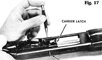
3. Remove the trigger guard retaining pin (Figure 17).
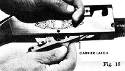
4. Draw the bolt rearward about 11/2 inches (Figure 18).
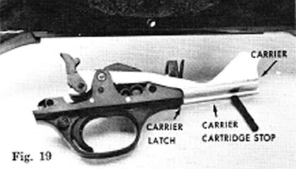
5. With your other hand trip the carrier latch, grasp the trigger guard (Figure 18) and remove it by forcing it slightly forward before attempting to lift it out of the receiver (Figure 19).
6. Ease the bolt forward again.
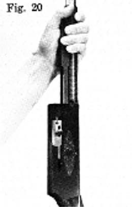
7. With the butt stock resting firmly on a workbench or table, grasp the action bar assembly and compress the action spring several inches (Figure 20).
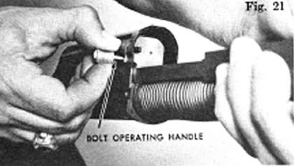
8. Remove the bolt operating handle with your other hand. Firm finger pressure removes it easily (Figure 21).
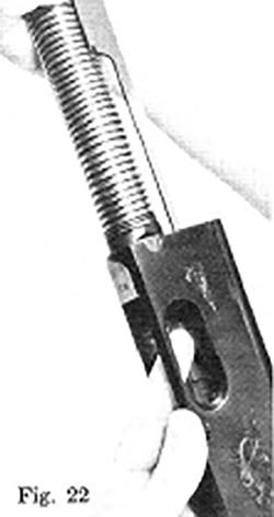
9. To remove the bolt and bolt slide ease the action bar assembly forward off the magazine tube while depressing the cartridge stop with your finger (Figure 22). The cartridge stop projects from the bottom of the bolt slide. Particularly notice how the double action bars separate from the bolt. This will help you during reassembly later.
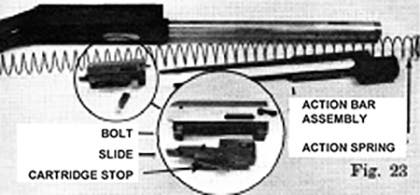
You can now easily clean all of these components as well as the inside of the receiver. (See Figure 23.) Again a good solvent is recommended. Further disassembly of the trigger group is not recommended.
NOTE: Do not apply large quantities of oil to the trigger group or other areas of the action. Excessive oil is not necessary and serves to collect dust and minute particles of dirt. Excessive oil could also soak into the stock; softening the walnut and loosening the stock. Only a very, very light film of fine quality gun oil is needed to protect these working parts.
REASSEMBLY OF THE ACTION
REASSEMBLY OF THE ACTION
Follow the steps below:
1. Slide the action spring onto the magazine tube, compress the action spring and start the action bar assembly onto the magazine tube. Grasp the action bar assembly keeping the spring slightly compressed.
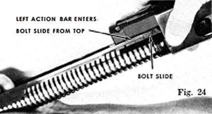
2. Assemble the bolt and bolt slide and align the action bars in their respective recesses in the bolt slide. This is done just forward of the receiver before the bolt is completely inserted into the receiver. Notice that the left (loading port side) action bar enters from the top of the bolt slide (Figure 24) while the right action bar attaches from the bottom (Figure 25).
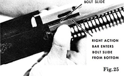
It is easiest to cant the bolt assembly to the left and attach the left action bar first, then rotate the bolt assembly to the right and downward until the right action bar is engaged.
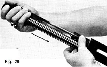
3. Keeping the action bars located in the bolt slide with your fingers (Figure 26) carefully orient the bolt assembly in the appropriate receiver channels and push rearward on the action bar assembly until the bolt assembly slides into the receiver.
4. Insert the bolt operating handle and gradually release pressure on the action bar assembly.
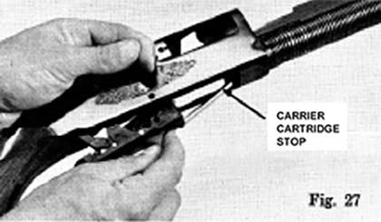
5. Draw the bolt partially rearward and insert the trigger group (Figure 27). Replace the trigger guard retaining pin. CAUTION: While inserting the trigger group be careful not to scratch the under surface of the receiver with the carrier cartridge stop. (This is the long, slender, unblued piece of metal which lies alongside the carrier; see Figure 27.) If you will tip the trigger group so that you introduce the carrier and the carrier cartridge stop into the receiver first, you can easily avoid scratching the receiver.
6. Lock the bolt open.
7. Replace the gas system (see dismantling and cleaning the gas system) and install barrel and forearm.
TWO OR MORE GUNS IN ONE BY USE OF EXTRA BARRELS
TWO OR MORE GUNS IN ONE BY USE OF EXTRA BARRELS
Use the same gun for multiple shooting conditions merely by changing from one barrel to another of different choke, length and rib. Barrels of the same gauge are completely interchangeable, and no special fitting or altering of the gas system is required. Thus, by merely buying another barrel, you have the utility of another gun at a fraction of the cost of a new gun . . . a duck gun becomes a skeet gun or a fine upland gun by the mere addition of an extra barrel.
NOTE: As pointed out earlier, you do not need a complete separate gun to shoot 3” magnums. An extra 3” magnum barrel is all that is needed. Simply interchange barrels. Altering the gas system is unnecessary. (See ‘To Shoot 3” Magnums’).
NOTE: With the 3 inch Magnum barrel installed the B-2000 is designed to function reliably with 3 inch Magnum shells. While no harm can come from shooting 2 3/4"Magnum loads in the 3 inch chambered Magnum barrel, it is not advised since the ejector mechanism built into the barrel extension of the 3” barrel to specifically eject 3” cartridges is not totally dependable upon ejection with the shorter cartridges. Should the shooter not mind an occasional hang up in the ejection port with the shorter 2 3/4"Magnum shells he indeed may also use them if desired. Please see your Browning dealer for barrel specifications available.
CLEANING SUGGESTIONS
CLEANING SUGGESTIONS
The correct procedure for cleaning your shotgun is as follows:
BE CERTAIN YOUR SHOTGUN IS UNLOADED
BE CERTAIN YOUR SHOTGUN IS UNLOADED
1. Dismount barrel so that it can be cleaned from the breech end.
2. Using a shotgun rod with tip and patch large enough for snug fit in bore, insert rod and patch in breech end of barrel and run back and forth through bore several times.
3. Inspect bore from both ends for leading by looking through bore toward light. Leading will appear as dull longitudinal streaks and is usually more predominant in the constriction area of the choke and just forward of the chamber.
4. Leading is minimal with today’s modern loads. If or when leading should become heavy, it can be removed with a brass bore brush. Use a good powder solvent such as Browning Liquid Gunsmith and scrub bore until leading is removed. To prevent brass bristles from breaking off, the brush should be pushed completely through bore before being withdrawn.
5. After leading has been removed, the bore should be wiped dry and then a slightly oiled patch run through it for preservation.
6. If the gun has been exposed to much dust, dirt, mud or water, the action and gas system should be stripped down and cleaned as outlined in this booklet.
7. Reassemble barrel and wipe all exposed metal surfaces with an oiled cloth making sure to wipe gun clean of all finger marks where moisture will accumulate.
8. The wood surfaces can also be wiped with Browning Gun Oil or they can be polished with any quality furniture wax.
SERIAL NUMBER: The serial number of your Browning 2000 Shotgun is found on the underside of the receiver, just forward of the carrier.
CHOKE MARKING
CHOKE MARKING
The choke of your barrel is indicated by a clearly defined mark stamped on the right hand side of the barrel. The code for the choke markings is as follows:
| Full | * |
| Improved Modified | *_ |
| Modified | ** |
| Improved Cylinder | **_ |
| Skeet | **$ |
| Cylinder | *** |
SERVICE OR REPAIR
SERVICE OR REPAIR
If your shotgun should require service or repairs we suggest you first contact a local authorized Browning Firearms Service Center. Your Browning Sporting Goods dealer can tell you the address of the Service Center nearest you or you may call or write our Consumer Information Dept. in Morgan, Utah - (801) 876-2711. Otherwise you may return your shotgun to our own repair facility for servicing. The address is:
Browning Service Department
3005 Arnold-Tenbrook Road
Arnold, Missouri 63010-4728
636-287-6800
800-322-4626
When returning your shotgun for servicing, please be sure to package it securely in a cardboard container. Send a letter to our Service Department clearly describing the trouble experienced and the repairs or alterations desired. If convenient, also enclose a copy of your letter with the gun.